Branch Current Method
In the branch current method Kirchhoff's voltage and current laws are used to solve for the current in each branch of a circuit. Once the branch currents are known, voltages can be determined.
STEPS
The following are the general steps used in applying the branch current method.
Step 1: Assign a current in each circuit it branch in an direction.
Step 2: Show the polarities of the resistor voltages according to the assigned branch current direction.
Step 3: Apply Kirchhoff's voltage law around each closed loop (Sum of voltages equal to zero).
Step 4: Apply Kirchhoff's current law at the minimum number of nodes so that all branch currents are included (Sum of currents at a node equals zero).
Step 5: Solve the equations resulting from step 3 and 4 for the branch current values.
CIRCUIT FOR DEMONSTRATING BRANCH CURRENT ANALYSES

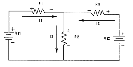
| First | The branch current I1, I2, and I3 are assigned in the direction as shown in figure-1. Do not worry about the actual current directions at this point. |
| Second | The polarities of the voltage drops across R1, R2 and R3 are indicated in the figure-1 according to the current directions. |
| Third | Kirchhoff's voltage law applied to the two loops gives the following equations. Equation 1: R1I1 + R2I2 ----VS1 = 0 for loop 1 Equation 2: R2I2 + R3I3 -----VS2 = 0 for loop 2 |
| Fourth | Kirchhoff's current law is applied to node A, including all branch currents as follows. Equation 3: I1 - I2 + I3 = 0 the negative signs indicates that I2 is out of the junction. |
| Fifth | The three equations must be solved for the three unknown currents, I1, I2 and I3. |
The three equations in the above steps are called Simultaneous Equations and can be solved by substitution.
BRANCH CURRENT METHOD EXAMPLE

Finding Current in each branch using branch current method.
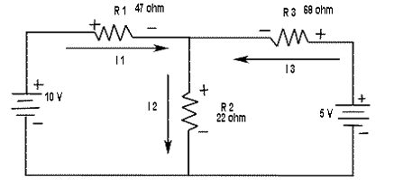
| Step 1: | Assign branch current keep in mind that you can assume any current direction at this point and that the final solution will have a negative sign if the actual current is opposite to the assigned current. |
| Step 2: | Mark the polarities of the resistor voltage drops as shown in the figure. |
| Step 3: | Applying Kirchhoff's voltage law around the left loop gives 47I1 + 22I2 - 10 = 0 Around the right loop gives 22I2 + 68I3 - 5 = 0 |
| Step 4: | At node A, the current equation is I1 - I2 + I3 = 0 |
| Step 5: | The equation are solved by substitution as follows. First find I, in terms of I2 and I3 I1 = I2 - I3 Now substitute I2 - I3 for I1 in the left loop equation. 47(I2 - I3) + 22I2 = 10 47I2 - 47I3 + 22I2 = 10 69I2 - 47I3 = 10 Next, take the right loop equation and solve for I2 in terms of I3 22I2= 5 - 68I3 I2 = (5 - 68I3)/22 Substituting this expression for I2 into 69I2 - 47I3 = 10 you get 69(5-68I3/22) - 47I3 = 10 (345 - 4692I3)/22 - 47I3 = 10 -260.27I3 = -5.68 I3 = 5.68/260.27 = 0.0218 A = 21.8 mA Now, substitute this value of I3 into the right loop equation. 22I2 + 68(0.0218) = 5 Solve for I2 I2 = (5 - 68(0.0218))/22 = 3.52/22 = 0.16 A = 160 mA Substituting I2 and I3 values into the current equation at node A, you obtain I1 - 0.16 + 0.0218 = 0 I1 = 0.16 - 0.0218 = 0.138 A = 138 mA |
