Types Of Antennas
Half Wave Dipole Antenna
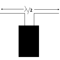
As shown in the given diagram, the half wave dipole consists of a conducting wire cut from the center where the input is provided in case of transmission or output is obtained in case of reception.
Current and Voltage Distribution
As shown in the given diagram, the current of the half wave dipole is minimum at the ends and at the center its maximum. The voltage is maximum at the ends and is minimum at the center.
Folded Dipole Antenna
As shown in the given diagram, the folded dipole antenna is designed from the two parallel conductor’s each equal to λ/2 of the operating frequency. The ends of the parallel conductors are joined together. The input to the folded dipole is provided by cutting one of the conductors from the center point and connecting the feeder with it.
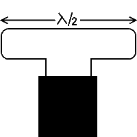
Folded dipole can be used for the purpose of transmission and reception. It is mostly used for the reception of Television, transmission and F.M transmission.
As the input impedance of the folded dipole is 300 nΩ, therefore it can be efficiently used with the twin wire cable with this cable of transmission line. The proper matching takes place and we get the maximum transfer of power between load and source.
Long Wire Un-Resonant Antenna
As shown in the given diagram, the long wire antenna consists of a conducting wire placed horizontally with the help of poles or mast, and supported by insulator and springs. The input is provided from one end and the other end of the long wire antenna is terminated to its characteristics impedance.
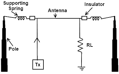
As the long wire antenna is terminated to its characteristic impedance therefore, the proper matching is carried out and no reflected energy will be present form load towards the source. The standing wave will be equal to the incident waves. The current and voltage wave forms will be in phase to each other.
Field Pattern
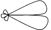
The given field pattern of the long wire antenna shows that the propagation of this antenna takes place in one direction. It means that it is unidirectional antenna.
As there is no reflected energy from the load towards the source, therefore, this type of long wire antenna which is terminated to its characteristic impedance is called non-resonator antenna.
Long Wire Resonant Antenna
As shown in the given diagram, the long wire antenna consists of a conducting wire placed horizontally with the help of poles or mast, and supported by insulator and spring. The input is provided from one end and the other end of the long wire antenna is kept non-connected.
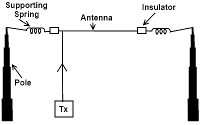
As the long wire resonant antenna is connected in such a way that input is provided from the one end and the other end is not connected to any thing or its matching is not carried out, therefore the incident and reflected both the waves will be present over it. As a result the transmission will be carried out from its both sides and the radiation pattern will be as follows
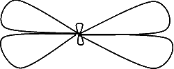
From the graph of the radiation pattern. It is indicated that the transmission is carried out from both the sides along horizontal axis. This graph also indicates that the maximum reception will be possible along the horizontal axis from the opposite ends. The long wire resonant antenna is a bi-directional antenna.
Isotropic Antenna
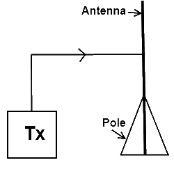
The isotropic antenna is said to be the type of antenna which radiates equally in all directions. This type of antenna is considered to be an ideal antenna and taken as a reference for most of the calculations related to propagation of E.M waves
Ferrite Rod Antenna
As shown in the given diagram, the ferrite rod antenna consists of a conducting wire wounded over the insulated former in the shape of coil. The open ends of the coil are used for the purpose of input. The former is placed around the ferrite rod in order to obtain the high Q of the output.
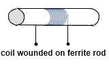
The ferrite rod is used to concentrate the magnetic flux of the E.M waves present in the surrounding. The maximum field is induced in the coil and the induced voltages are developed as an output signal for the reception. The size of ferrite should not be smaller than the coil so that the Q factor may not reduce. The size of ferrite rod should not be longer than the size of coil very much because it will also disturb the Q factor of the coil and we will get the high sharpness of the Q factor. The coil should be kept at λ/4 distance of the desired frequency at the ferrite rod so, that maximum output signal should be obtained at the output.
Loop antenna
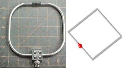
The loop antenna shown in the below diagram is designed from a conducting wire in the given shape. It has two types
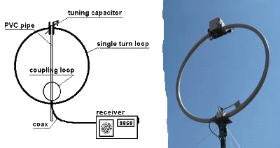
- Circular Loop Antenna
- Square Loop Antenna
The design of square loop antenna is exactly same as for the folded dipole antenna except the distance between the two conducting wires of the antenna. The upper conducting wire of the loop antenna is kept λ/2 of the operating frequency and the lower conducting wire is also of the same size. The signal is provided from the center of the one of the conducting wire, and it radiates in the antenna. It means that if antenna is located horizontally the radiation pattern in its horizontal plane will be the figure of zero. If the antenna is located horizontally and we are looking at it vertical plane, it will represent the figure of eight (8) for its radiation pattern and so on.
The loop antenna is high directional antenna. The antenna is also used mostly for commonly in the directional finder equipment.
Rhombic Antenna
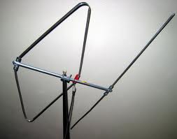
As shown in the given diagram, the rhombic antenna consists of two conducting wires tilted at the angle of 70 degree and kept in such a way that it adopts the shape of algebraic figure of rhombus. Input is provided from the one side of the wire and output end is terminated with its characteristics impedance with the help of pure resistor for proper matching. The value of the resistor is from 600 Ω to 800Ω and its power rating is about 2 watts. The rhombic antenna is unidirectional antenna. Its directivity is quite high. It’s mostly used for the purpose of transmission.
Arrays Antenna
All the elements of antenna which takes part in the reception and transmission is called the arrays. It can also be explained as all those elements of the antenna which generates electromagnetic waves when voltage or current is flowing through it in case of transmission and produces voltages and current when electromagnetic waves are present in case of reception.
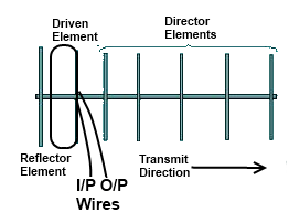
These elements of antenna may be directly connected with the source or load and my not be directly connected with the source or load.
Types of Arrays
There are two types of arrays antenna
Driven Array
The driven array is also called the driven element. It is the element of the antenna which is directly connected with the source or the load. In the given diagram the folded dipole is the example of the driven array.
Parasitic Array
The parasitic arrays are also called the parasitic elements. These are the elements of the antenna which are not directly taking part in reception and transmission but these elements indirectly increase the strength of the signal for transmission or reception.
In the given diagram reflector and directors are the parasitic arrays example.
Discone Antenna
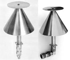
As shown in the given diagram, the discone antenna consists of a metallic disc and a metallic cone. The cone is situated under the metallic disc. This type of antenna is an Omni directional antenna and it is used for both transmission and reception. The metallic disc of the antenna works as reflector. The discone antenna is mostly used in mobile communication system for its performance.
Slot Antenna
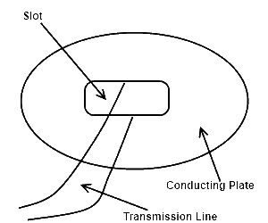
The slot antenna consists of a metallic plate in which a rectangular slot is made. The distance of the broad dimension of rectangular slot is equal to λ/2 of the operating frequency. The slot antenna works exactly like folded dipole antenna. Its radiation pattern is also same as for dipole antenna. The slot antenna is mostly used for the purpose of reception bt it can be used for the purpose of transmission quite effectively.
One of the major advantages of slot antenna is tis design which is very robust. It is also quite economical to use.
Helical Antenna
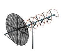
As shown in the diagram, the helical antenna consists of a mast or pole at which the supporting rod of antenna is located. There is a square shaped conducting mesh which works as a ground plan for the antenna. After the mesh a helix is used which works as the radiator of the antenna . the distance between the center of the mesh and the first turn of the helix is λ/8 of the operating frequency.
The distance between the adjacent turns of the helix is kept as λ/4 and the diameter of the each turn of the helix is λ/3 of the operating frequency. The helix is normally made of copper.
Modes of Operation
There are the following two modes of operation of helical antenna
Normal Mode
In the normal mode of operation the radiation takes place perpendicularly to the antenna or perpendicular to the axis of the helix in case of transmission. The reception will also take place at the stage when the E.M waves are perpendicular to the axis of the helix.
Circular Mode
In the circular mode of operation the radiation takes place along the antenna or along the axis of the helix in case of transmission. The reception will also take place at the stage when the E.M waves are along the axis of the helix.
The polarization in case of circular mode of operation will be the circular polarization. The helix antenna works as unidirectional antenna.
Parabolic Antenna
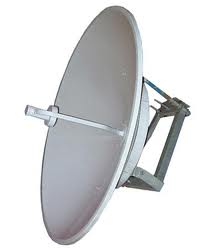
As shown in the given diagram, the parabolic antenna consists of a metallic reflector made in the shape of geometric figure of parabola. In case of reception it is the characteristics of the parabolic antenna that all the energy received is reflected back at the point known as focal point. This focal point is a virtual point and the received energy is collected by the horn type wave guide from there the reception. As the signal produced by the parabola reflector is basically very weak signal but when it is collected by the focal point, the strength of the signal increases to the proper level required for the reception.
The focal point of the parabolic antenna remains the same for that antenna designed . if we change the design of the parabolic antenna the focal point is also changed and the energy will be now collected from some other distance as compared to previous one.
In case of transmission all the rays produced by focal point will travel parallel after reflection from parabolic reflector.
The length of the path for all the rays reflected from parabolic reflector and travelled from the focal point to the reflector will remain the same at any given straight line behind the focal point.
