Filter Circuits
To remove the AC components or filter them out in a rectifier circuit, a filter circuit is used. A filter circuit is a device that is used to remove the A.C components of the rectified output but allows the D.C components to reach the load. A filter circuit is in general a combination of inductor (L) and Capacitor (C) called an LC filter circuit. A capacitor allows A.C only and an inductor allows D.C only to pass. So a suitable L and C network can effectively filter out the A.C component from the rectified wave.
A filter circuit consists of passive circuit elements i.e., inductors, capacitors, resistors, and their combination. The filter action depends upon the electrical properties of passive circuit elements. For example, an inductor allows the D.C. to pass through it. But it blocks A.C. On the other hand, a capacitor allows the AC to pass through it. But it blocks the D.C. Some of the important filters are given below.
- Inductor Filter
- Capacitor Filter
- T Filter
- LC Filter
- π Filter
Inductor Filter

This type of filter is also called a choke filter. It consists of an inductor L which is inserted between the rectifier and the load resistance RL. The rectifier contains A.C. components as well as D.C components. When the output passes through the inductor, it offers a high resistance to the A.C component and no resistance to D.C components. Therefore, A.C components of the rectified output are blocked and only D.C components are reached at the load.
Inductor filters, also known as inductor-input filters or simply LC filters, are electronic circuits used to filter and smooth electrical signals. They consist of an inductor (L) and a capacitor (C) connected in series or parallel. Here are some of the pros and cons of using inductor filters:
Pros:
- Noise Reduction: Inductor filters are effective at reducing high-frequency noise and electromagnetic interference (EMI) from electrical signals. They are often used in power supplies to eliminate or reduce voltage spikes and ripple.
- Improved Signal Quality: By removing high-frequency noise and spikes, inductor filters can help improve the overall quality and stability of electrical signals, making them suitable for sensitive applications.
- Energy Storage: Inductors store energy in their magnetic fields, which can be beneficial in certain applications. They can act as energy reservoirs, providing additional power during brief periods of high demand.
- Simple Design: The basic design of an inductor filter is relatively simple, consisting of only two passive components (an inductor and a capacitor). This simplicity makes them cost-effective and easy to implement.
Cons:
- Size and Weight: Inductors tend to be physically larger and heavier than other passive components, such as resistors and capacitors. This can be a drawback in compact or lightweight electronic devices.
- Limited Frequency Range: Inductor filters are most effective at filtering high-frequency noise, but their effectiveness decreases at very low or very high frequencies. Choosing the right inductor and capacitor values is crucial to target specific frequency ranges.
- Energy Loss: Inductors have resistance and can dissipate some energy as heat. This can result in energy loss in the filter, which may be a concern in energy-efficient applications.
- Complex Calculations: Designing inductor filters can be more complex than designing simple passive filters. Calculating the appropriate values for the inductor and capacitor to achieve the desired filtering effect can require expertise.
- Limited Voltage Ratings: Inductors have voltage ratings, and exceeding these ratings can lead to saturation or damage. Care must be taken when designing and using inductor filters to ensure they can handle the voltage levels present in the circuit.
In summary, inductor filters are valuable components in electronics for their noise-reduction capabilities and signal quality improvement. However, they also come with limitations such as size, energy loss, and complexity, which must be considered when incorporating them into electronic circuits. The choice to use an inductor filter should be based on the specific requirements and constraints of the application.
Capacitor Filter

In this filter a capacitor is connected across the load during the rise of the voltage cycle it gets charged and this charge is supplied to the load during the fall in the voltage cycle. This process is repeated for each cycle and thus the repel is reduced across the load. It is shown in the above Figure. It is popular, because of its low cost, small size, less weight, and good characteristics. Useful for loading up to 50mA as in transistor radio battery eliminators.
Capacitor filters, also known as capacitor-input filters or simply RC filters, are electronic circuits used to filter and smooth electrical signals. They consist of a capacitor (C) and a resistor (R) connected in series or parallel. Here are some of the pros and cons of using capacitor filters:
Pros:
- High-Pass Filtering: Capacitor filters are effective at blocking low-frequency signals while allowing high-frequency signals to pass through. They are commonly used to eliminate ripple and provide DC voltage in power supply applications.
- Compact and Lightweight: Capacitors are typically smaller and lighter than inductors, making them suitable for applications where space and weight constraints are critical.
- Low Cost: Capacitors are relatively inexpensive and readily available, which makes them a cost-effective choice for filtering applications.
- Simple Design: The basic design of a capacitor filter is straightforward, with only two passive components (a capacitor and a resistor). This simplicity facilitates easy integration into electronic circuits.
Cons:
- Voltage Droop: In capacitor filters, the output voltage can experience a gradual decrease over time due to the discharge of the capacitor. This can be a limitation in applications requiring a constant voltage output.
- Limited Filtering Range: Capacitor filters are most effective at filtering low-frequency noise and ripple. They are less effective at attenuating very high-frequency noise. Additional filtering stages may be required for comprehensive noise suppression.
- Energy Storage: Unlike inductors, capacitors do not store energy. This means that they cannot provide additional power during brief periods of high demand, which could be a drawback in certain applications.
- Voltage Ratings: Capacitors have voltage ratings, and exceeding these ratings can lead to capacitor failure, which may result in circuit damage or safety hazards. Proper selection of capacitors with suitable voltage ratings is essential.
- Complex Ripple Reduction: Achieving a specific level of ripple reduction may require careful selection of resistor and capacitor values. Designing precise capacitor filters can be more complex than it initially appears.
In summary, capacitor filters are valuable components in electronics for their high-pass filtering capabilities and compact design. They are particularly useful in power supply applications to reduce ripple. However, they have limitations such as voltage droop and limited high-frequency noise filtering, which should be considered when choosing them for a specific application. The choice to use a capacitor filter should align with the filtering requirements and constraints of the circuit.
T Filter
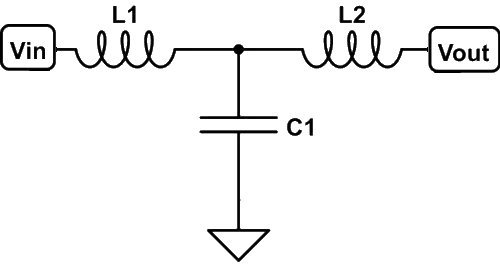
A T filter, also known as a "T-section filter" or "T-type filter," is a passive electronic filter configuration that consists of three components arranged in the shape of the letter "T." These components typically include two series-connected resistors and a capacitor connected between them. T filters are primarily used for high-pass or low-pass filtering applications, depending on how they are configured. Here's a breakdown of T filters, including their definition, explanation, characteristics, pros, and cons:
Definition and Explanation:
- Components: A T filter consists of two resistors (R1 and R2) or conductors (L1 and L2) connected in series and a capacitor (C) connected between the junction of the resistors and ground, forming the shape of a "T."
- Filter Type: The type of filter (high-pass or low-pass) depends on the arrangement of the components. In a high-pass T filter, the input signal is applied at one end of the resistor chain (R1), and the filtered output is taken across the capacitor (C). In a low-pass T filter, the input signal is applied across the capacitor (C), and the filtered output is taken at the junction of the resistors (R2) or conductor (L2).
Characteristics:
- Frequency Response: The frequency response of a T filter is determined by the values of the resistors and the capacitor. High-pass T filters allow high-frequency signals to pass through while attenuating low-frequency signals. Low-pass T filters allow low-frequency signals to pass through while attenuating high-frequency signals.
- Filter Slope: The slope of the filter's response (rate of attenuation) depends on the values of the resistors and the capacitor. Steeper slopes can be achieved with appropriate component values.
Pros:
- Simplicity: T filters have a straightforward design with only three passive components, making them cost-effective and easy to implement.
- Customizable Response: By choosing specific resistor and capacitor values, you can tailor the filter to meet your frequency response requirements.
- Versatility: T filters can be used for both high-pass and low-pass filtering, offering versatility for various applications.
Cons:
- Limited Bandwidth: T filters have a limited bandwidth, meaning they are optimized for a specific range of frequencies. Achieving wideband filtering may require more complex filter designs.
- Energy Loss: The resistors in T filters introduce energy losses in the form of heat, which can be a concern in applications requiring high efficiency.
- Component Values: Precisely designing a T filter for specific cutoff frequencies may require careful selection of resistor and capacitor values. Component tolerances can affect filter performance.
In summary, T filters are passive electronic filter configurations used for high-pass or low-pass filtering. They offer simplicity, customization, and versatility but have limitations in terms of bandwidth and energy losses. The choice of a T filter or any filter type depends on the specific filtering requirements and constraints of the application.
LC Filter

In the inductor filter, the ripple factor is directly proportional to the load resistance. On the other hand in a capacitor filter, it varies inversely with the load resistance. Hence if we combine the inductor filter with the capacitor the ripple factor will become almost independent of the load filter. It is also known as inductor input filter, choke input filter, L input, or LC-section.
In this circuit, a choke is connected in series with the load. It offers high resistance to the AC components and allows the DC component to flow through the load. The capacitor across the load is connected in parallel which filters out any AC component flowing through the choke. In this way, the ripples are rectified and a smooth DC is provided through the load.
Pros:
- Effective Filtering: LC filters are highly effective at filtering and shaping electrical signals, allowing you to selectively pass desired frequencies while attenuating unwanted ones. This is crucial in applications where signal quality is essential.
- Low Power Dissipation: LC filters are passive components, meaning they don't consume power themselves. This is beneficial for applications where power efficiency is a concern.
- Simple Design: They have a relatively simple design, consisting of just two passive components—an inductor and a capacitor. This simplicity makes them cost-effective and easy to implement in various circuits.
- Energy Storage: Inductors in LC filters can store energy in their magnetic fields, which can be useful in applications requiring energy buffering or transient response improvement.
- Versatility: LC filters can be configured as high-pass, low-pass, band-pass, or band-stop filters, making them versatile for a wide range of filtering needs.
Cons:
- Component Sizing: Properly selecting the values of the inductor and capacitor to achieve the desired filtering effect can be challenging, especially for complex filtering requirements. Designing precise LC filters can be complex.
- Limited Bandwidth: LC filters have limited bandwidth and may not effectively filter signals with frequencies far from the cutoff frequency. They are best suited for applications within a specific frequency range.
- Losses: Both the inductor and capacitor can introduce some losses into the circuit, including resistive losses in the inductor and dielectric losses in the capacitor. This can affect overall circuit efficiency.
- Size and Weight: Inductors can be relatively large and heavy, which can be a limitation in compact or portable electronic devices. Smaller form-factor components may be preferred in such cases.
- Complexity for Multistage Filters: In applications requiring multiple stages of filtering, managing the interaction between stages and achieving the desired overall response can be complex. It may require careful design and analysis.
In summary, LC filters are valuable components in electronics for their effective frequency-selective filtering capabilities. They are commonly used to remove noise and shape signal waveforms. However, their design and component selection can be challenging, and they have limitations such as limited bandwidth and potential losses. The choice to use an LC filter should align with the specific filtering requirements and constraints of the circuit.
CLC or Pi Filter

It consists of one inductor and two capacitors connected across each end. The three components are arranged in the shape of the Greek letter Pi. It is also called a capacitor input Pi filter. The input capacitor C1 is selected to offer very low reactance to the repel frequency hence major parts of filtering are done by C1. Most of the remaining repels are removed by the combining action of L and C2. This circuit gives a much better filter than the LC filter. However, C1 is still directly connected across the supply and would need a high pulse of current if the load current is large. This filter is used for low-current equipment.
CLC and π (pi) filters are common types of passive electronic filters used for various applications. Here are the pros and cons of each:
CLC Filter (Capacitor-Inductor-Capacitor):
Pros:
- Effective Filtering: CLC filters provide effective filtering by combining the advantages of both inductive and capacitive elements. They can offer good attenuation of both high and low frequencies.
- Low Power Dissipation: Like other passive filters, CLC filters do not consume power themselves, which can be advantageous for power-efficient applications.
- Simple Design: They have a relatively simple design, consisting of three passive components—an inductor and two capacitors. This simplicity makes them cost-effective and easy to integrate.
Cons:
- Component Sizing: Selecting the appropriate values for the inductor and capacitors can be challenging, especially for complex filtering requirements. Precise design may require careful consideration.
- Size and Weight: Inductors, which are part of CLC filters, can be relatively large and heavy, which can be a limitation in compact or portable electronic devices.
- Complexity for Multistage Filters: When multiple stages of filtering are needed, managing the interaction between stages and achieving the desired overall response can be complex.
π (Pi) Filter:
Pros:
- Effective High-Pass or Low-Pass Filtering: π filters can be configured as either high-pass or low-pass filters and are particularly effective at one of these tasks. They offer good attenuation in their chosen passband.
- Simple Design: Like CLC filters, π filters have a relatively simple design, consisting of three passive components—two resistors and a capacitor or two capacitors and a resistor.
Cons:
- Limited Bandwidth: π filters are optimized for either high-pass or low-pass operation, which means they are less versatile compared to CLC filters in terms of filtering frequency ranges.
- Energy Loss: The resistors in π filters introduce energy losses in the form of heat, which can be a concern in applications requiring high efficiency.
- Component Values: Precisely designing a π filter for specific cutoff frequencies may require careful selection of resistor and capacitor values.
In summary, the choice between CLC and π filters depends on the specific filtering requirements of a given application. CLC filters offer more versatility in terms of filtering different frequency ranges but may have larger components. π filters are effective in their chosen passband but have limited bandwidth and introduce energy losses through resistors. Careful design and component selection are crucial for both types of filters to achieve the desired filtering characteristics.
Amazon Affiliate Links