Voltage Multipliers
In voltage multiplier circuit two or more peak rectifiers are cascaded to produce a d.c voltage equal to multiplier of the peak input voltages Vp i.e., 2Vp, 3Vp, 4Vp.
HALF WAVE VOLTAGE DOUBLER
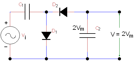
A voltage multiplier, whose output d.c. voltage is double the peak a.c. input voltage, is called a voltage doubler below Figure shows the circuit, of a half-wave voltage doubler.

During the positive half-cycle of the input signal, the diode DI conducts and diode D2 is cut off, charging the capacitor CI up to the peak rectified voltage i.e., Vm. During the negative half-cycle, diode, D1 is cut off and diode D2 conducts charging capacitor C2. It may be noted that during negative half cycle, the voltage across capacitor C1 is in series with the input voltage. Therefore the total voltage presented to capacitor C2 is equal to 2Vm during the negative half cycle.
On the next positive half cycle, the diode D2 is non-conducting and the capacitor will discharge through the load. If no load is connected across capacitor C2, both capacitors stay charged at their full values (i.e., C1 to Vm and C2 to 2Vm). It may be noted that both the diodes D1 and D2 have a peak inverse voltage (PIV) of 2Vm each.

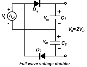
Above Figure shows another voltage doubler circuit known as full-wave voltage doubler. In this circuit during, the positive half cycle of a.c. input voltage, diode D1 conducts charging capacitor CI to a peak voltage Vm with polarity. The diode D2 is cut off at this time.
During the negative half cycle the diode D2 conducts (while D1 is at cut-off) charging capacitor C2 to Vm. If there is load connected across the output, then the output voltage is equal to 2Vm. However, if the load is connected, then the voltage would be less than 2Vm.
VOLTAGE TRIPLER
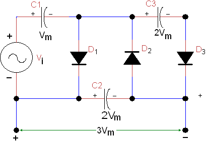
During the first positive half cycle, the capacitor C1 charges through diode D1 to a peak voltage Vm. During negative half cycle, capacitor C2 charges through diode D2 to twice the peak voltage 2Vm developed by the sum of the voltages across capacitor C1 and the input signal.

During the second positive half cycle, the diode D2 conducts and the voltage across capacitor C2 charges the capacitor C3 to the same 2Vm peak voltage. The triple output taken across C1 and C3 connected in series, the output voltage is three times the input voltage.
VOLTAGE QUADRUPLER
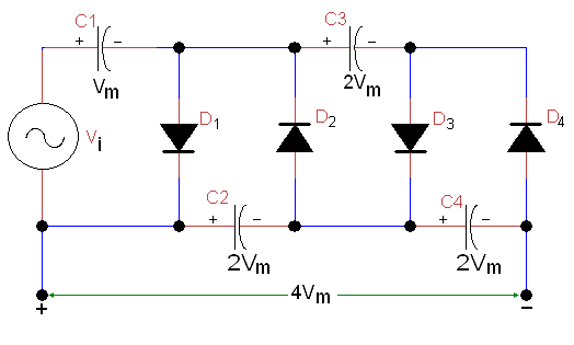
The addition of still another diode-capacitor section to the voltage Tripler produces an output four times the peak voltage. The circuit diagram is shown in below Figure.

In such type of circuit C1 charges to Vm, through D1, C2 charges through D2, C3 and C4 charges through D4, C2, C3 and C4 charges to 2Vm. The 4Vm output is taken across C2 and C4.
The ripple frequency is twice the input frequency.
Theoretically there is no upper limit to the amount of voltage multiplication that can be obtain. But practically there is a limit the reason is that total amount of capacitance becomes large to maintain the desired d.c. output except extremely light loads.
Application
Voltage multipliers are used in high voltage, low current applications such as for accelerating purpose in a cathode ray tube. Generally these are used where both the supply voltage and load are maintained constant.
