Thyristor Gate Firing Networks
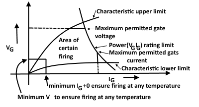
For safe and certain firing the gate firing signal must be fitted in the area bounded by shaded lines, as shown in the figure below.


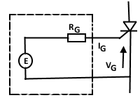
A firing network consists of a Transformer for isolating a resistor R1 to limit gate current and a resistor R2 to limit gate voltage. When the thyristor is in the OFF state.
Thevenine’s Equivalent circuit for firing network.

Applying KVL in the above circuit
E = IG RG + VG
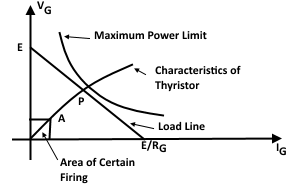
Hence the load line can be drawn as

When the firing signal is initialed the gate current will grow along the line of characteristic until the steady state point “P” is reached. However, before this point, the thyristor will have turned ON, most likely in the region of point “A”.
The parameters of the firing network must be so chosen that the load line is above point “A” but within the maximum power limit.
Requirements of Firing Circuits
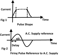
To turn on the thyristor positively in the shortest time, it is desirable to have a gate current with a fast rise time up to the maximum permitted value. This rise time is best achieved by pulse techniques, where a firing circuit generates a fast rise pulse of sufficient length to allow the anode current enough time to reach its latching value.
Advantages of the use of Pulse signals
- The advantage of the pulse is that much less power is dissipated in the gate compared to a continuous current.
- The instant of firing can be accurately controlled.
An essential requirement of the firing circuit in A.C. supply application is that the thyristor shall be turned on at a time related to the A.C. voltage phase. Also, the phase of the firing pulse in relation to the A.C. supply voltage zero must be capable of variation.
Typically firing circuit output pulse characteristics

A pulse length of 10µs with a rise to 2V in 1µs may be sufficient for many applications. Some applications may require a pulse length of 100µs.
The firing circuit resets itself normally after the first pulse to give a succession of pulses to the end of the half cycle as shown in figure-2. In the rectifier circuit conditions may not be right for conduction to take place at the first pulse, the second and successive pulse being available to turn on the thyristor.
Many rectifier configurations require the simultaneous firing of two thyristors, the cathodes of which are at different potentials to overcome this problem, the final stage of the firing will be a transformer with two or more isolated outputs.
The injection of gate current when the thyristor is reverse-biased it will increase the leakage current and is best avoided.
Typical Firing Circuits

The above figure shows a crude firing arrangement. Its object is to control the load voltage to the waveform shape as shown below.

The gate current is given by
ig = Vsupply / R
As sinusoidal voltage raises from zero the gate current will eventually reach a level such as to turn on the thyristor, this occurring at an angle (say) “α”.
Limitation of Crude Firing Arrangement
The circuit shown in Fig-A has many limitations & for these limitations, it is not used practically, these limitations are,
- The turn-on angle will vary from cycle to cycle as temperature and other changes take place in the thyristor.
- Turn on will be shown and cannot occur near zero voltage.
- The firing angle “α” cannot exceed 90o.
Practical firing Circuit Using Transistor
Practical firing circuits use the switching action of the transistor to generate a triggering pulse.

Simple Firing Circuit Using Transistor
The diode D1 rectifies the sinusoidal input into pulsating D.C.
Zener diode “Z” clips the peaks of pulsating D.C voltage to supply a level voltage to the R1C1 series circuit.
The resistor R2 drops the difference between the supply voltage and the zener diode.
Working
The reference voltage to the base of the transistor is determined by the resistor chain S. Initially with zero voltage on C1 the transistor is held off, but when the voltage on C1 at the emitter reaches a high enough level, the transistor starts to conduct. Feedback action via the transformer winding raises the base current so the transistor turns hard on, discharging C1 rapidly into the thyristor gate via the transformer.
Practical firing circuit Using UJT

Simple Firing Circuit Using Unijunction Transistor
Working
Initially, C1 is not charged, so UJT is OFF, or in other words, it does not allow any current to pass through it. As the voltage on capacitor C1 reaches a particular value, then the unijunction transistor will change to its conducting state, allowing C1 to discharge into the thyristor gate. The rapid discharge of C1 gives a fast-rise pulse into the thyristor gate.
Note: it should be noted that in both circuits, the voltage on the capacitor C1 will rise exponentially at a rate determined by the value of R1. Both of the transistor firing circuits will reset after C1 is discharged, building up to give a second and further pulse.
Control of the Firing Angle
At the zero point in the A.C. supply cycle, the ckt will completely discharge; hence the initial growth of voltage at C1 is timed from the supply zero. By adjustment of R1, the time of the first output pulse can be controlled up to 180o delay in a waveform.
Firing Circuits for Complex Systems
The more sophisticated firing circuits contain many more stages in their electronic circuits. Such circuits may, for example, rely on the interrelationship between a ramp voltage and the external control voltage to initiate accurately, at the same time in each cycle, the start of the pulse generator.

Firing System for Complex Systems
For applications other than those connected with a fixed frequency supply, the firing circuits include oscillators to initiate the pulse starts and finishes.
Control Features of Complex Firing Circuits
The more complex systems utilizing thyristors as the power control elements will include
- Closed loop links
- Poly phase supply
- Automatic control of current or motor torque level.
- Inhibiting loops to ensure against mal function of operation due to simultaneous firing of different groups.
