Backward Wave Oscillator & Circulator
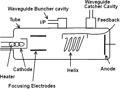
As shown in the given diagram, the backward wave oscillator is made of tube in which heater, cathode, helix, feedback conductor and focusing electrodes and anode is located. The waveguide cavity resonator is used for the input trigger known as buncher cavity resonator. At the output end there is another waveguide cavity resonator which is known as catcher cavity resonator and used for the output of backward wave oscillator.

Working
When we switch on the circuit, the heater will starts to heat up. As a result the thermionic emission from cathode will start. The electrons will move from cathode and will be focused by the focusing electrodes. It will be collected by the anode and it will travel back to the cathode in order to complete its path.
When the input signal is applied to the buncher cavity, the waveguide buncher cavity will excite. This will induce the voltages at the input end of the helix present inform of the buncher cavity. As the induce voltage is A.C signal in the helix, it will have a positive and negative half cycles. If we consider the input negative half cycle at the helix, the electrons emitted from the cathode will be repelled back at the input of the helix which will result to from a bunch.
Now for positive half cycle these electrons bunch will speed up and induce the voltage in the next ring of the helix. This induced voltage will be stronger than the previous one. Finally at the output end of the helix the induce voltage will be so much strong that, it will excite the catcher cavity. The output will be obtained from the catcher cavity with the help of loop coupling. The feedback conductor is placed over the helix in order to overcome the damping effects and to maintain the oscillation.
Circulator

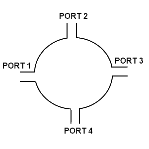
As shown in the given diagram, the circulator is a piece of circular wave guide which is covered from the open ends with the conducting plates. The four ports are designed for the input and output signals in such a way that each port is 90^o away from the other one.
Working of Circulator
As the microwave signal propagation with the help of E-Field and H-Field, therefore, the circulator works as a closed path for different signals to be propagated through a single junction. It works for the one input signal to be distributed by the more than one path. It also works for the reception and transmission of signal to close the transmission path during reception and to close the reception path during transmission.
