Understanding Waveguide Mode: A Guide to Signal Propagation
In the world of telecommunications and information technology, the efficient transmission of signals is paramount. Understanding the intricacies of signal propagation is key to optimizing communication systems. One of the crucial aspects of this process is the "waveguide mode." In this article, we will delve into the concept of waveguide mode and its significance in signal propagation.
What is Waveguide Mode?
Waveguide mode refers to a particular method of guiding and propagating electromagnetic waves or signals. It is commonly used in various devices and systems, including antennas, optical fibers, and microwave transmission lines. The waveguide itself serves as a conduit or channel through which these waves can travel.
Types of Waveguide Modes
There are several types of waveguide modes, each with its unique characteristics and applications:
- TE Mode (Transverse Electric Mode)
- TM Mode (Transverse Magnetic Mode)
- Hybrid Modes
TE Mode (Transverse Electric Mode)
In the TE mode, the electric field vector is entirely transverse to the direction of propagation. This means that there is no electric field component along the direction of wave travel. TE modes are often employed in waveguides where it is crucial to eliminate electrical interference.
The TE mode is subdivided further into the following modes.
TE10 Mode

TE10 Mode In the TE10 mode, the figure indicates the number of half wavelengths (λ/2) across the broad dimension of the electric field. The second figure indicates that the length of the narrow dimension is less than (λ/2) of the magnetic field.
The TE10 means that during propagation through the waveguide, the electric field is perpendicular to the direction of propagation. It is equal to λ/2 across the broad dimension and the magnetic field is less than λ/2.
TE11 mode

TE11 Mode In the TE11 mode, the first figure indicates the number of half-wave lengths (λ/2) across the broad dimension of the electric field. The second figure indicates the length of the narrow dimension (λ/2) of the magnetic field.
The TE11 means that during propagation through the waveguide, the electric field and magnetic field are perpendicular to the direction of propagation. It is λ/2 across the broad dimension and the magnetic field is also λ/2 across the narrow dimension.
TE20 Mode

TE20 Mode In the TE20 mode, the first figure shows the number of full wave length λ across the broad detention of the electric the second figure indicates that the length of the narrow dimension is less than the λ of the magnetic field. The TE20 means that the electric field is perpendicular to the direction of propagation.
TE01 Mode

TE01 Mode In the TE01 mode, the first figure indicates the number of less than half wavelength across the broad dimension of the electric field. The second figure indicates that the length of the narrow dimension is equal to the half wavelength λ/2 of the magnetic field. The TE01 means that the electric field is perpendicular to the direction of propagation.
TM Mode
When the propagation takes place through the waveguide in TM mode, the magnetic field is perpendicular to the direction of propagation and an electric field is in the direction of propagation and electric field is in the direction of propagation. In TM mode it is also called that magnetic flux is transversed to the direction of propagation.
The TM mode is further subdivided into the following modes.
TM11 mode

TM11 mode As shown in the given diagram in TM11 mode both the (a) and (b) dimensions of the waveguide are equal to λ/2 of the operating frequency. The signal is carried by the magnetic field components and electric field components are in the direction of propagation.
TM21 Mode

TM21 mode As shown in the given diagram in TM21 mode the (a) dimension is equal to the complete wavelength of the operating frequency and the (b) dimension is equal to half the wavelength of the operation frequency. The magnetic field carries the signal. The magnetic field component carries the signal through the waveguide. And electric field components are in the direction of propagation.
Hybrid Modes
Hybrid modes in waveguides refer to a category of waveguide modes that exhibit a combination of both transverse electric (TE) and transverse magnetic (TM) characteristics. These modes are characterized by having both electric field (E) and magnetic field (H) components that are non-zero and oriented in different directions with respect to the direction of wave propagation. Hybrid modes are particularly important in various waveguide applications, and they can be further subdivided into several subcategories based on their field distributions and characteristics. Here are the main sub-divisions of hybrid modes:
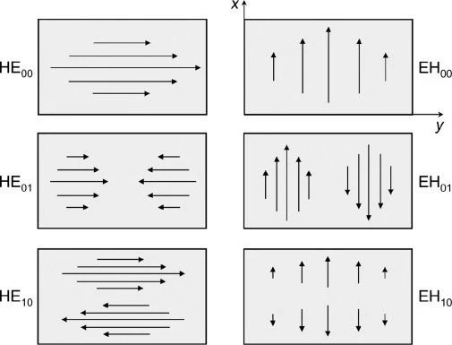
Hybrid Modes of Waveguide Signal Propagation HE Modes (Hybrid Electric Modes):
HE modes are hybrid modes where the dominant field component is the electric field (E), which is primarily transverse to the direction of propagation. These modes typically have a relatively stronger E-field component compared to the H-field component. HE modes are often designated with two subscripts, such as HE1, HE2, etc., indicating the order of the mode.
EH Modes (Hybrid Magnetic Modes):
EH modes are hybrid modes where the dominant field component is the magnetic field (H), which is primarily transverse to the direction of propagation. These modes have a stronger H-field component compared to the E-field component. EH modes are also designated with two subscripts, such as EH1, EH2, etc., indicating the order of the mode.
Mixed-Mode:
Mixed-mode hybrid waveguide modes are those where both the electric and magnetic field components are significant and contribute to the mode's characteristics. In these modes, the E and H fields are oriented in complex patterns that can vary depending on the specific mode and the geometry of the waveguide.
Higher-Order Hybrid Modes:
Both HE and EH modes can have higher-order versions (e.g., HE11, EH21) that correspond to different field distributions and higher propagation modes within the waveguide structure. These modes have additional nodal planes and antinodal planes for the electric and magnetic fields.
Hybrid Plasmonic Modes
In some cases, hybrid modes can also occur in plasmonic waveguides, where the waveguide structure involves interactions with surface plasmon polaritons (SPPs). These modes combine the characteristics of plasmonic modes and traditional waveguide modes.
Tunneling Hybrid Modes
Tunneling hybrid modes are a specific type of hybrid mode that can occur in waveguides with very thin dielectric layers. These modes are characterized by their ability to "tunnel" through the dielectric barrier, allowing for efficient energy transfer across the barrier.
The choice and characteristics of hybrid modes depend on the specific waveguide geometry, material properties, and the application's requirements. Engineers and researchers often analyze and design waveguide structures to harness the unique properties of hybrid modes for various purposes, including signal transmission, energy transfer, and sensing applications.
Importance of Waveguide Modes in Signal Propagation
Understanding and utilizing waveguide modes are essential for several reasons:
Signal Integrity
Waveguide modes enable the controlled and guided propagation of signals, reducing the chances of signal distortion or loss. This is particularly critical in high-frequency applications where signal fidelity is paramount.
Minimizing Interference
By selecting the appropriate waveguide mode, it is possible to minimize interference from external sources. TE and TM modes, for instance, can effectively isolate signals from unwanted electrical or magnetic influences.
Signal Directionality
Waveguide modes allow for precise control over the direction in which signals propagate. This directional control is crucial in applications like antennas and satellite communication, where signal timing is essential.
Transitioning to Efficient Signal Propagation
In conclusion, waveguide modes play a pivotal role in the efficient propagation of signals in various communication and transmission systems. Their ability to guide electromagnetic waves while minimizing interference is invaluable in ensuring reliable and high-quality signal transmission.
As technology continues to advance, a deeper understanding of waveguide modes will lead to even more efficient and robust communication systems. Whether you're working in telecommunications, optics, or microwave engineering, the knowledge of waveguide modes is a fundamental asset in your pursuit of signal excellence.