Sampling Quantizing Coding & Multiplexing
In 1933, Nyquist gave his theory of sampling, which states"If sampling is done at a rate higher than twice the highest frequency contained in the signal, it is possible to receive the original signal from the sampled signal by passing it through a low-pass filter having cut-off equal to the highest frequency in the original signal".
This is known as Sampling Theorem or Nyquist's Sampling Criteria.
If sampling Frequency = fA
Highest signal Frequency =fS
Then
fA > fS
The frequency band used in telephone system is 4 KHz, i.e., 300 Hz to 3400 Hz. This frequency band for telephone system has been specified internationally. Thus according to sampling theorem, the sampling frequency, interval between two consecutive samples for the telephone signal is calculated as follows.
Sampling frequency = fA = 2 x 4000 = 8000 Hz
Sampling interval or Time per frame = TA = 1/ fA
TA= 1/8000- 125µs

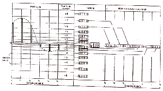
The sampling of the telephone signal is shown in the figure.
In the figure shown above, a telephone signal after passing through a low-pass filter is fed to an electronic switch. A chain of electronic switches (one for each channel) controls the sampling process. The electronic switch is governed by precise timing circuits. The low-pass filter limits the frequency band by suppressing frequencies higher than half the sampling frequency i.e., 4000 Hz. The electronic switch samples the telephone signal at a rate of 8000 samples per second. The time interval between two consecutive samples is 125 (is. The output of the electronic switch is a PAM signal.
QUANTIZING

The sampling process represents the analog waveform of the voice signal by a series of pulses. The amplitude of each pulse is proportional to the instantaneous value of the signal. This operation is called Pulse Amplitude Modulation (PAM) and the signal is still in an analog form. For the ease of transmission, the sampled signal is further processed, i.e., converted into digital form. For conversion into digital the sampled signal is quantized. In this process each sample is compared to a standard scale of discrete values and is given a binary number representing its approximate amplitude.)
In practice, the number of quantizing intervals used is 256 (+1 to +128 in the positive range of the telephone signal and —1 to — 128 in the negative range). This increased quantizing numbers reduces signal distortion on the receiving side. Because on the transmitting side, several different analog values fall within the same quantizing intervals while on the receiving side one signal value is recovered for each quantizing interval which correspond to the midpoint of the quantizing interval. Due to this, small discrepancies occur in the samples on the transmitting and receiving side. The discrepancy for each sample can be up to half a quantizing interval. Thus a quantizing distortion i.e., noise appears on the receiving side. This distortion decreases as the number of quantizing intervals is increased.
To simplify the explanation of quantizing principle, 16 equal quantizing intervals (+1 to +8 in the positive range and -1 to —8 in the negative range) are shown in the figure.
ENCODING
The quantized sample is next converted into a binary code word by the encoder circuit. The encoder allocates an 8-bit PCM word to each individual sample. An 8-bit binary code is used for the 256 quantizing intervals (128 + 128 = 256 = 28). The PCM words therefore have 8 bits (Binary digiTS). The first bit of all PCM words used for the positive quantizing intervals is a "1", the first bit of all PCM words used for the negative quantizing intervals is a "0". Bits 2, 4, 6 and 8 in every 8-bit PCM word are inverted for Transmission as per CCITT recommendations. The quantized sample is encoded as shown in the figure.

DECODING
Signal amplitude Vout is allocated to every 8-bit PCM word on the receiving side. The value of Vout corresponds to the midpoint of the particular quantizing interval. The decoding of the PCM words take place in the order in which they are received and is converted to pulse amplitude modulated (PAM) signal. The PAM signal is then fed to a low-pass filter, which reproduces the original analog telephone signal.
MULTIPLEXING
After sampling, quantizing and encoding the input signal into digital form, it must be transmitted to its destination. It is not economical to send a single voice channel over a single transmission channel. Therefore, in telephonic network transmission many individual channels are multiplexed over a single transmission channel. Thus multiplexing is to send a number of telephone signals consecutively in repeated cycles.
Thus in the process of multiplexing the 8-bit PCM word of one telephone signal is followed by the PCM words of all other telephone signals. These signals are arranged in consecutive manner, i.e., one after the other separated in time. Hence the name time division multiplexing (TDM) is used for this process.
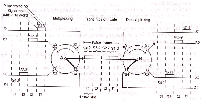
The multiplexing process is fully electronic and is shown in the figure No.4.8. For simplicity four telephone signals have been shown. These signals are sampled by switch "A" in sequential order, i.e., it moves from one signal to the next. At the output of switch "A" a PCM time division multiplex signal is available.

DEMULTIPLEXING
The demultiplexing process is also fully electronic. The time division multiplexing signal is received at the receiving side and the individual PCM signals are recovered from it. As shown in the figure No.4.8 the 8-bit PCM words are distributed to the corresponding outputs. The switch "B" synchronized with switch "A", distributes the PCM words to the four outputs.
