Transmission Line
The transmission line is defined as the path of carrying alternating electrical energy from source to load.
For example, the wire used between T.V antenna and a television set or the wire used between a transmitter antenna and a transmitter are known as transmission lines.
Types
There are the following types of transmission lines.
- Balanced two wire
- Co-axial Cable
- Waveguide
- Microstrip
- Fiber Optic
1. Balance Two Wire Line
As shown in the given diagram the two-wire transmission lines consist of figures A, B, and C. Each construction for the given figure is given below.
In this type of construction for two-wire transmission lines, the insulated spacers are used in order to maintain the distance between the transmission lines or between the two conducting wires equally throughout.
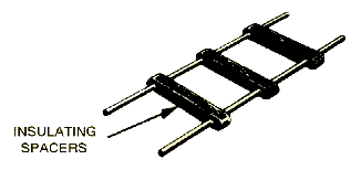
Balance Two Wire Line - Insulating Spaces In this type of transmission line, the two conducting wires are kept parallel to each other with the help of plastic material. This is used throughout between the conducting wires.
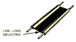
Balance Two Wire Line - Low Loss Dielectric In this type of transmission line, the rubber piping is used in circular rectangular, or square shapes. The two conducting wires are kept inside the rubber at opposite sides of the piping. These conducting wires run throughout the construction and remain parallel to each other

Merits
There are the following merits of balance two-wire lines.
- The cost of the two-wire transmission line is very low compared to other types of lines.
- Designing the open two-line transmission line is quite simple and easy too.
- Open two wire lines are capable of handling high power.
- Demerits
- The external interference of the signal in open two-wire lines is more as compared to other types of transmission lines.
- Due to external interference, the output at the load end of the two-wire transmission line will be noisy.
- Using the two-wire transmission lines in twisty paths is quite difficult.
- A formula for finding out the characteristics impedance of an open two-wire transmission line is given below.
- It cannot be used on very high frequencies because it will generate a skin effect.
Impedance
Zo = 276 log10 2D/d
Here d stands for the diameter of the wire.
D stands for the distance between two wires from its aerials.
Zo stands for characteristics impedance
2. Co-axial Cable
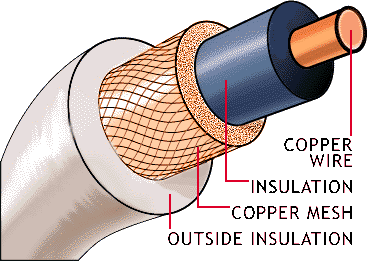
As shown in the given diagram the co-axial cable consists of an inner conducting wire made of copper, over this conducting wire the coating of polyethylene or taplon material is carried out. Then it is enclosed in the braided wire in the shape of mash. The outer surface of this wire is enclosed in a plastic jacket.
Merits
There are the following merits of co-axial cable.
- As the outer conductor (braided wire) is grounded, therefore the possibility of external interference is minimized. The output of the load end will be less noise.
- The co-axial cable is used for high frequencies transmission.
- This type of transmission cable can be easily used if the path of energy from source to load is twisty or complicated.
- Co-axial cable occupies less space as compared to two-wire lines.
- The conductor which carries the energy from source to load is protected from dust, rust, etc. due to proper insulation.
Demerits
There are the following demerits of the co-axial cable used as a transmission line.
- This type of transmission line is costly with respect to two-wire lines.
- Designing of co-axial cable is difficult as compared to two-wire lines.
- This type of transmission line handles low-power transmissions.
- The formula for the impedance is
Impedance
Zo = 233 log10 D/d
Where Zo stands for characteristics impedance.
D stands for the internal wire diameter of the braided wire.
d stands for the diameter of the inner conductor.
3. Microstrip Line
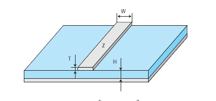
A microstrip is simply a copper track running on one side of the PCB while the other side is a plain ground plane. The formula will give you the characteristic impedance of the track, as well as the effective dielectric constant based on the geometric parameters. The table provides usual values for 1.6 and 0.8 mm thick PCBs as well as for the standard FR4 substrate or the most advanced Rogers R04003.
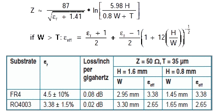
Construction
As shown in the above diagram the microstrip consists of a conducting plate made of copper which works as an earth plate in the circuit. There is a thick coat of insulating material over the copper plate which is made of fiberglass or polystyrene. This insulated plate works as a dielectric in the microstrip line. At the top of the insulated plate, one or more than one strip of the best conducting material are plated which is made of gold, aluminum, etc.
Merits
There are the following merits of the microstrip line.
- Very high frequency.
- Small size
- Low weight.
- Losses are minimum.
- This type of transmission line is used for very high frequency.
- Microstrip lines are used in integrated circuits where the distance between load and source is very short.
- As the path of energy is made of very good conductors like gold, therefore the losses of energy are minimum possible.
- The weight of the microstrip line is low.
Demerits
There are the following demerits of the microstrip line.
- The cost of a microstrip is very high as compared to a co-axial and two-wire line.
- The microstrip line cannot be used as a transmission line when the distance between the source and load is long.
- This type of transmission line cannot be used in twisty paths between source and load.
Losses of Transmission Line
There are the following losses of transmission lines.
Radiation Losses
When the high-frequency current or voltage waveform flow through the transmission lines, the magnetic field expands and collapses around the transmission lines at the same rate as the input frequency. As we know that around the magnetic field, there is also an electric field, therefore high-frequency radiation causes the attenuation in the energy provided by the source towards the load.
Conductor heating
When the current flow takes place through the transmission line, the conducting wires of the line start to become heat up. This heating of the lines reduces the energy provided by the source to the load.
Dielectric Loss or Heating
As the transmission lines are composed of two parallel conducting wires and current flow takes place through the line. The potential difference exists between the two lines. This potential difference causes the leakage current through the dielectric. As a result, the heating of dielectric material takes place which reduces the energy provided by the source to load.
