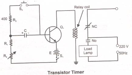
Transistor Timer
In electronics timers the output of the timing element is used as a trigger pulse for BJT, FET and UJT, the active devices element signal is amplified and this way this signal is used for the load control switch. In load control system, electromechanical relays as well as solid-state devices are also used, the switching device turn ON and OFF the load without and interception.

In the above figure a transistor timer circuit is shown. in which R1,R2 and emitter of the transistor work as timing element, while the transistor work as triggering element, relay work as load switching element, which control the out put.
With closing switch S the timer interval start, at the same time transistor, Relay coil and RC components are start energiesing, due to energizing a relay the normal ON contact of the relay move towards the normal OFF contact and out put load turn ON.
The timer works on the capacitor “C” Resistor R1, R2 and emitter network, this network is arrange in such way that they provides forward bias voltage to the transistor base terminal (break over voltage). The base current through “C” decreases due to which base voltages also decreases, which at lost turn OFF the transistor, same time the collector, emitter junction reverse bias and the relay coil also de-energies and the mechanical control of the relay again move from normal OFF state to normal ON state.
If the reset-push-switch pressed, the capacitor start discharging through R3 and again capacitor start charging and the cycle start again. The timer duration changes by changing the values of the capacitor and resistors.
