AC/DC Converters – Rectifiers
Rectification
AC/DC converters serve as rectifiers. They convert ac to dc in a number of industrial, domestic, agricultural, and other applications. Rectifiers are used as stand-alone units feeding single and multiple dc loads and as input stages of ac systems because of their virtually unlimited output power and fine controllability. Their speed of response is usually adequate to handle electromechanical transients occurring in motor drives and power suppliers.
AC/DC line-commutated converters or, as they also called, converters with natural commutation or passive rectifiers, are the most usual choice for applications, where a single-phase and three-phase supply is available. This is due to simplicity of the circuits requiring a minimum number of active and passive components. Thyristors are the main line-commutated power switches. The term “line-commutated” describes the type of commutation, i.e. the transfer of current from one conducting element to the next, as a function of the mains voltage. To turn on a thyristor, an injection of a current pulse into its gate is required.
In low-power applications, vehicle, medicine, and household devices, where there is no ac supply or where reactive current and harmonics caused by a line commutation would be unreachable, it is accepted to employ forced commutatedconverters having a more complex circuitry and sometimes involving higher losses. A special situation exists also with dc and ac loads, where the response of a line-commutated converter may be insufficient to cope with the stringent dynamic and energy efficiency demands and where an additional converter supplied by a dc link and operated with a high switching frequency is necessary. For these purposes active rectifiers are developed.
The basic rectifier topologies are given in the circuit diagrams of Fig. 1 where the load is presented by the dc motors. The systems built on diodes are called uncontrolled rectifiers, and those built on thyristors and transistors are known as controlled rectifiers because their dc output can be changed. The rectification processes are quite varied; accordingly, there are different types of rectifying circuits
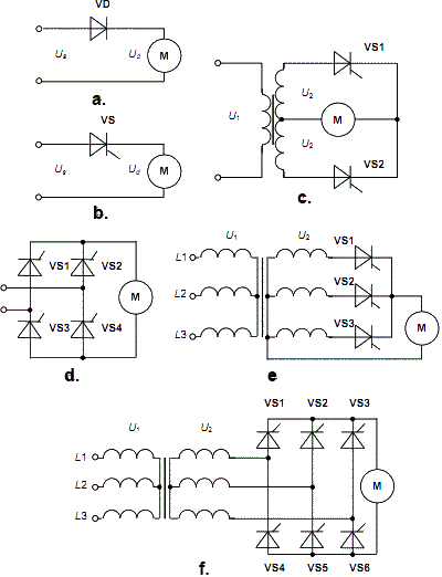
- midpoint (M) and bridge (B) rectifiers
- single-phase (M1, M2, B2) and three-phase (M3, B6) rectifiers
- half-wave (1 pulse per supply period) and full-wave (2, 3, 6 pulses) rectifiers
Rectifier data
Rectifiers differ by the shape of dc signal, ripples, and efficiency that depends on rms, average, and amplitude values of voltage, current, and power. Their power range is very wide, from milliwatts to megawatts. Low-power devices operate usually from a single-phase supply while high-power rectifiers are mainly used in a three-phase configuration. In the table below, the main data of different non-controlled rectifier circuits with a resistive load are given.
The apparent rms power Ps, phase voltage Us, and current Is supply the rectifier directly, through chokes, or via a transformer. In the last case Us = U2, Ps = P2. The average rectified load power Pd, voltage Ud, and current Id are the pulsating dc signals with 1, 2, 3, or 6 pulses per supply period T. Parameters kU, kI, kP, kR, and kF are called voltage, smoothed current, power, reverse, and forward circuit factors.
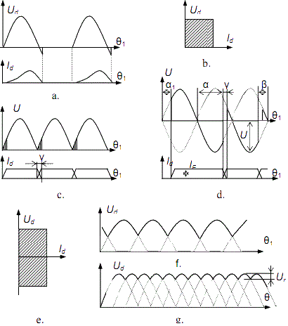
The ripple factor kr of the output waveform is usually determined by the rectified peak-to-peak ripple voltage swing Ur (see Fig. 2 below). The peak inverse voltage UR and forward current IF of each rectifier device depends on the circuit type. The power factor of a rectifier defines the ratio of the real average active power Pd to the apparent power Ps, which is the product of the rms voltage and the rms current, therefore φ is a phase displacement angle of current relative to voltage. For the given voltage, the rms current drawn is
Is = Pd/Uscosφ
This shows that the power factor and the current are inversely proportional values. The current flows through the utility distribution and transmission lines, transformers and so on exciting the losses in their resistances. If the losses grow, possibly to the point of overloading, harmonic currents may cause resonance conditions in transmission lines. The supply voltage waveform will also be distorted, adversely affecting other linear loads, if a significant portion of the load supplied by the consumer absorbs power by mean of distorted currents. This is the reason why consumers prefer unity power factor that draws power at the minimum value of the rms current.
Single-phase rectifiers
At power levels below a few kilowatts, for example in residential applications, the loads are supplied by a single-phase supply source. Commonly used simple half-wave single-phase rectifier circuits (M1) are represented in Fig. 1, a, b. The resulting output voltage and current waveforms of the half-wave diode rectifier are shown in Fig. 2, a. Here
θ1 = ω1t
ω1 = 2πf1,
where ω1 is the angular frequency, f1 is the frequency of the supply voltage, and t is time. During the positive alternation of the ac sinusoidal wave, the anode of the diode VD is positive and the cathode is negative, the diode conducts since it is forward-biased. The positive alternation of the ac will then appear across the load motor M. During the negative alternation of ac cycle, the anode becomes negative while the cathode is positive. The diode is reverse-biased by this voltage and practically no current will flow through the load. Therefore, no voltage appears across the load. Such type of the converter is called a half-wave rectifier because the negative half cycles have been clipped off. Since the load voltage has mainly a positive half cycle, the load current is direct and discontinuous, meaning that it flows in only one direction and has breaks. Thus, the rectifier is capable of operating in the first quadrant of the current-voltage plane, as Fig. 5, b shows; hence, it is called a single-quadrant converter.
In the case of resistive load, Ud is always positive and ac line current (the same as the rectified current Id) has the half-sine shape and flows in phase with voltage. The loads like motors have the properties of the resistive-inductive load; hence, Ud goes negative shortly, and ac line current (the same as Id) is out of phase with the voltage. When inductance aspires to infinity, the current waveform distorts and becomes almost rectangle.
The two thyristor single phase fullwave rectifier (midpoint rectifier or M2) is shown in Fig. 1, c. It produces a rectified rippled output voltage and current for each alternation of the ac input, as shows Fig. 5, c, for the case of the diode circuit. Inductive load causes current overlap designated by the overlap angle y. The rectifier utilizes a center tapped transformer that transfers alternating source voltage to the diode rectifier circuit. The anodes of each device VS1 and VS2 are connected to the opposite ends of the transformer secondary winding. The cathodes are then joined together to form a common positive output. The load motor M is connected between the common cathode point and the center tap connector of the transformer. The transformer, two diodes or thyristors, and the load form a complete path for the current.
By adjusting the thyristor firing angle α between 0 and π, a user can run the machine in both directions, but the load current and the motor torque are unidirectional as Fig. 5, d, displays. Thus, the rectifier is capable of operating in two quadrants of the current-voltage plane: the first quadrant is the rectifying mode of operation and the fourth quadrant supports the inverting mode of the operation. Therefore, it is a two quadrant converter (Fig. 5, e). As long as the converter cannot produce the negative output current, the motor control signals and braking modes should be limited. In the inverting mode, it is more convenient to express the firing angle in terms of the angle of advance from the end limit of the interval available for successful commutation than as a delay a from the beginning of the interval. This angle of advance shown in Fig. 5, d, is usually denoted as R. Then,
α + β = π
cos α = - cos β
To form a full wave single-phase bridge rectifier (B2), four diodes or thyristors have to be interconnected, as Fig. 1, d, shows. Using four devices instead of two, this design eliminates the need for the center tap. During the performance of a bridge rectifier, two diodes are forward biased in each alternation of the ac input voltage. When the positive alternation occurs, devices VS2 and VS3 are forward biased, while VS1 and VS4 are reverse biased. The conduction path follows from the ac source, through VS2, the load, then through VS3, and back to the source. This causes the same alternation to appear across the load. During the negative alternation, the current flows from the source through VS1, via the load, then through VS4, and back to the supply line. This causes the second alternation to appear across the load in the same direction as the first alternation. This means that voltage developed across the load is the same for each alternation. As a result, both alternations of the input appear as the output across the load and pulsating current flows via the dc output. The timing diagrams and the current voltage plane of the circuit are the same as for the full wave rectifier.
Replace VS2 and VS4 by the pair of capacitors, named C1 and C2. In this half-bridge topology, a voltage doubling is obtained. VD1 charges C1 during the positive alternation of the supply voltage and
VD2 charges C2 during the negative alternation. On the output of the rectifier, the sum of both voltages is presented.
Three-phase rectifiers
The three phase three diode rectifier circuit (midpoint rectifier, M3) produces a purer direct voltage than the single-phase rectifier circuits do, thus wasting less power. It is preferable to use a three-phase supply source, except at a fractional kilowatt, if such supply is available. In Fig. 1, e, the phases L 1, L2, and L3 of the three-phase source are connected to the anodes of thyristors VS1, VS2, and VS3 via the transformer. The load motor M is connected between the cathodes of the thyristors and the neutral of the transformer. When the phase L 1 is at its positive value, maximum conduction occurs through VS1 since it is forward biased. No conduction occurs through VS1 during the negative alternation of the phase L 1. Other thyristors operate in a similar manner, conducting during the positive ac input alternation and not conducting during the associated negative ac alternation.
The rectifying diagram of a thyristor three-phase three diode circuit is shown in Fig. 5, f. In the case of resistive inductive load, the current continues through the diode or thyristor after the voltage has changed its sign. For that reason, the thyristor does not close at the zero voltage instant, but remains open. By adjusting the thyristors firing angle, the negative voltage may be obtained, thus it is a two quadrant converter again.
A commonly used six pulse counterpart of this rectifier circuit is represented in Fig. 4, f. This three-phase bridge rectifier (B6) uses six diodes or thyristors. The anodes of thyristors VS4, VS5, and VS6 are connected together at one point, while the cathodes of VS1, VS2, and VS3 are joined at the other point. The load is connected across these two points. Therefore, the device connected to the most positive voltage will conduct in cathode group; the other two will be reverse biased. As well, the device connected to the most negative voltage will conduct in anode group; the other two in this group will be reverse biased. At least two devices are simultaneously in the open state here and at least one device from each group must conduct to facilitate the flow of the motor current. The voltage ripple is low because the output voltage consists of six pulses per voltage period (Fig. 2, g). The switching order of the thyristors in Fig. 4, f, is VS1+VS6, VS6+VS2, VS2+VS4, VS4+VS3, VS3+VS5, VS5+VS1. This circuit does not require the neutral line of the three-phase source; therefore, a delta connected source as well as a wye connected one could be used. Again, it is a two quadrant rectifier. If the load possesses high inductance, the forward current continues on the negative anode voltage and the switching off of the device is delayed. Since the previously opened devices are not closed after the opening the next devices, it is possible that three or even four devices are open during the commutation process. This means that there is more than one open diode in the cathode or anode group and the current re-switches from one phase to another.
Dual rectifiers
In the previous circuits, the polarity of the load voltage may be changed, but the direction of the load current remains constant. In Fig. 3, a, the back-to-back connection of the two midpoint rectifiers has been produced to build a dual controlled system. This is a four quadrant dual rectifier because the negative current as well as the negative voltage may be produced here by the properly firing angle control (Fig. 3, b). Here, while thyristors VS1, VS2, and VS3 pass the current, a rectifier operates in the first and fourth quadrants whereas since thyristors VS4, VS5, and VS6 pass the current, the second and the third quadrants are active.
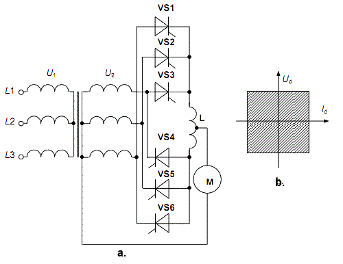
In Fig. 4, the anti-parallel connection of the two bridge rectifiers has been arranged to provide the four-quadrant operation. Such circuit is by far the most common industrial four-quadrant dc system and is used in many demanding applications where rapid control is required. Usually, they incorporate additional features to enhance the safety of operation and to improve the control transients.
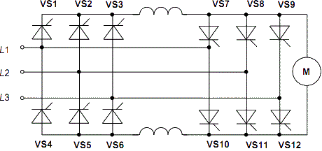
Today, dual converters with anti-parallel thyristors are produced in large numbers in the form of very compact units covering a wide power range from a few kilowatts to tens of megawatts. For the highest ratings, modular designs with air- and water-cooled heat sinks are available.
Active rectifiers
The use of diode and thyristor rectifiers leads to the problems of electromagnetic compatibility (EMC). Diodes and thyristors are the major contributors to power and current distortion problems, resulting in poor overall power factor, heating effects, device malfunction, and destruction of other equipment. It is remarkable that harmonics generated by rectifiers fall into the frequency spectrum up to about 3 kHz. They are conducted back into the power system producing a continuous distortion of the normal sinusoidal current waveform. The distortion frequencies are multiplies of the
Along with the growing pulse number of rectifiers, the frequencies of high order harmonics increase whereas their relative magnitude decreases. Therefore, the trace of the input current becomes more sinusoidal, and the output current is smoothed better. On the contrary, when the firing angle of the rectifier grows, harmonic frequencies and their magnitude do not change, but the phase shift of harmonics increases relative to the supply voltage. This effect causes the consumption of reactive power from the supply lines with the power factor decreasing. As a result, the demand for high quality power supply grows in the provision of unity power factor.
The recent standardization in EMC specifies limits for harmonic distortion, which may be met with a diode and thyristor rectifier circuit, accomplished by passive filters on the mains side. These, however, may be rather large and expensive. Further, in some EMC sensitive applications, the occurrence of harmonics in the rectifier, although filtered towards the supply mains, may disturb the operation of the whole system.
As an alternative, active rectifiers have been proposed. Interest in active rectifiers has grown rapidly over the decade due to some of their important advantages, such as power regenerative capabilities, dc voltage adjustment, low harmonic distortion of input currents, and high power factor.
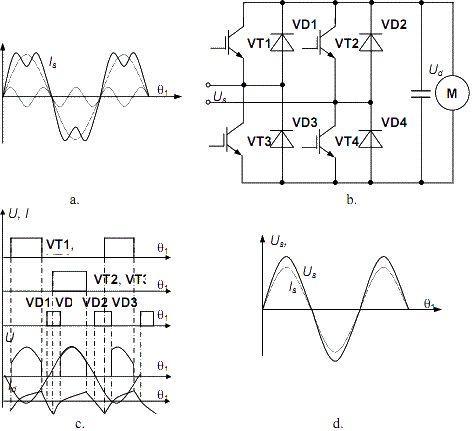
Active rectifiers like those shown in Fig. 5, b, are built on transistors, which, unlike diodes and thyristors, are the full controlled electronic devices with possible high frequency performance. Mains would be connected here via inductors to the phase terminals Us while Ud represents the dc output. This single-phase full bridge can be used as a rectifier and an inverter; thus, it permits bidirectional energy transfer, which is useful for applications with energy recovery. However, the circuit contains twice the amount of the switches compared to the passive rectifier.
A variety of control strategies have been invented for this type of converters and their operational principles differ essentially. Although many control methods are known and implemented, there are two ways of circuit performance in terms of the active rectifier. According to the first of them, the classical self commutated bridge rectifier passes a positive current without affording any control function. To pass a negative current for the motor braking, the transistors must be open in the switching mode. As far as the second way is concerned, the transistor bridge rectifies a current and controls the rectified voltage, whilst the freewheeling diodes pass the negative current in the regeneration period without voltage control, as shows Fig. 5, c, for all diodes simultaneously. In both cases, current may be positive and negative. Clearly, the gate adjustment of the switches is more complicated than this of thyristors because of the need in synchronization with the supply net and specific inductor; thus driving effort is somewhat higher.
Fig. 5, d, depicts the waveforms of mains voltage (solid) and mains current (dotted). Due to the sinusoidal shape of current, there would be no harmonic content. Furthermore, the zeroing phase angle between voltage and current traces avoids the occurrence of first harmonic reactive power. At the same rectified power, the rectifier input current has a significantly lower amplitude and rms value compared to a passive rectifier.
The topology of the three-phase Vienna rectifier is shown in Fig. 6, a; it can be characterized as follows. Each phase has an inductor on the supply side. The output represents a circuit with a controlled dc voltage and center point. It is advantageous that due to this division of the output voltage, the switches will need lower blocking voltage and thus better conduction characteristics can be used.
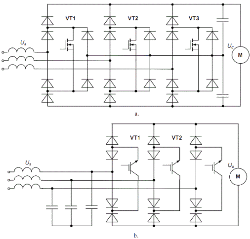
There is one controllable switch per phase: MOSFETs are depicted. Together with the surrounding four-diode bridges, they operate as bi-directional switches. When turned on, they connect the respective mains phase to the dc center point via the two diodes and the inductor, which makes the letter magnetize. When turned off, the inductor demagnetizes into the dc load through the freewheeling diodes connected to the positive and negative load terminals, respectively.
The circuit in Fig. 6, b, is again connected to the three-phase mains via one inductor per phase. Contrary to the Vienna rectifier, capacitors are located on the mains side of the converter and a dc voltage is adjusted between the positive and negative load terminals on the output side of the rectifier. The circuit uses bi-directional switches consisting of diodes and transistors: IGBTs are depicted in this case. Rectifying and inverting modes of operation are possible here, similarly to the previous circuit. In the rectifying phase, the switches are off, whereas during the inverting phase a pair of switches is on.
Summary
A single-phase half-period rectifier is the simplest one. Nevertheless, it has inadequate secondary current shape, very high ripple level, and very low power factor.
The main disadvantage of the two-diode midpoint rectifier is the requirement of a center-taped transformer.
A single-phase bridge rectifier uses the transformer and semiconductor devices more effectively; its current shape is more sinusoidal. That is why it is the best decision for low-power (up to 1 kW) applications.
Single-phase rectification results in two identical pulses per cycle in the rectified dc-side voltage, whereas three-phase rectification in three and more such pulses occurs. Therefore, three-phase rectifiers are superior in terms of minimizing distortion in line currents and ripple of the load voltage. Low degree of the transformer use and low power factor are the main disadvantages of the three-phase three-diode rectifier. Nevertheless, sufficiently high quality of rectified voltage with small ripples is its main advantage.
The three-phase bridge rectifiers are predominant because of their good technical properties: low ripple, high power factor, simple topology, and low price. Today they are used both in powerful and in small-power supplies as well as in AC/AC converters with a dc link.
Active rectifiers outperform the passive rectifiers with the following characteristics:
- Occurrence of harmonics in supply current is actively minimized
- in operation, the intermediate circuit is charged during the whole mains period with rectified sinusoidal supply current in phase with the supply voltage; this way, the maximum active power is available through a given mains fuse
- Rectified voltage and current are controlled thus the output is independent of the supply voltage over a wide range; this helps to overcome possible problems of unstable supply voltage and there is no necessity to manually pre-select the input voltage
- Only few and small passive components are required
It can be expected that this technique, which up to now is used rather seldom, will gain importance in the near future.
