Magnetic Bubble Memories
Magnetic bubble memories use small magnetized areas, called bubbles to represent data bits. An alternating electric field causes the bubbles to shift down the register. A constant magnetic field must also be supplied by an external magnet. Magnetic bubble memories are non-volatile, i.e. the magnetic bubbles do not disappear when power is turned off. CCD memories must include a battery if data is to be retained after power is is turned off. Most magnetic bubble memories require an external magnet. The CCD's are completely monolithic and can be manufactured with out the additional mechanical fabrication of magnetic assembly. Bubble memories are rapidly being introduced and size up to 10-20 million bits would make them more cost effective compared to magnetic disks.
Magnetic Surface Storage Devices
Magnetic surface storage devices provide a large capacity auxiliary memory required for digital computers. Some magnetic storage devices are mentioned as under:
- Magnetic Tape Storage
- Floppy Disk Storage
- Magnetic Disk Storage
- Magnetic Drum Storage
- Magnetic Core Storage
Magnetic Tape Storage
Magnetic tape storage is sequential access memory and is capable of having a very large capacity at a very low cost. Magnetic tape is a plastic tape about ½ inch wide, coated with a magnetic surface, identical to the tape used in home recording. The quality of material used in however much higher than that used in domestic purposes. The material used for coating is ferric oxide. The tape is wound on reels and passes from one reel to another past a read/write head. The reels are available in different sizes and hold 200, 600 1200 or 2400 ft of tape. The mechanism shown in Figure 1 is much faster and has more precise control of tape movement as compared to the house hold tape devices.
information is stored on tapes in frames, as shown in figure 1. The number of tracks may be seven or thirteen and each of these bits is known as a character. In a seven track tape 6 data bits are accompanied by a parity bit. The parity bit may be a 1 or 0 so that total number of 1's in a character is odd. During reading the parity is checked and the parity bit is not used again, and when data is written the parity bits is written and checked by a read-after-write operation. Data is transferred to and from the CPU in blocks which are separated along the tape by inter block gaps which allows the tape to reach the required speed for read/write operations. The information is thus stored in files or records.
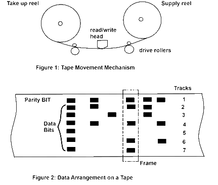
The recording density on magnetic tape ranges from 200 to 1000 characters per inch. The number of characters on the tape will depend on the number of records or files, since the gaps take up space. A standard tape of 2400 feet length can have up to about 2 ½ million characters.
Floppy Disk Storage
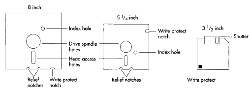
The floppy disk is a flexible plastic base disk. The floppy disk comes in an envelop as shown in figure 2 and it can be easily plugged in the drive mechanism as a tape cassette. The disk is interred in the drive with the envelope in place. This is because the envelope provides protection to the recording surface which is about 100µ in thick layer of magnetic oxide. The read/write head assembly comes in actual contact with the recording material. There is an index hole of about 0.1 inch diameter about 4 cm from the center of the disk to indicate the start of the track. A written track is 0.012 inch wide and standard track spacing is 48 inch. The number of tracks is 77. Most floppy disk use an address system like hard disks, where the disk drive track and sector are given. The normal capacity of a floppy disk is 1.4 MB. The speed of rotation is approximately 360 R.P.M.
Magnetic Disk Storage
Magnetic disk storage is based on the same physical phenomena as that of magnetic drum. Their external characters as seen by the system designer are essentially the same. They differ in mechanical structure.
The basic structure of a small storage is as shown in figure 3. The metal disk coated with ferromagnetic material rotates under one or more read/write heads. The speed of rotation is typically 1800 or 3600 R.P.M. The latest magnetic disk storages have speed up to 7200 R.P.M.
The read/write heads work on the same principle.
Following different arrangements are possible.
One Head Per Track System:
The disk is divided into several concentric tracks which store information. Both sides of the disk are used. The number of heads is mounted on the both sides of the disk, one for each track. This system is most widely used in single disk systems.
Comb Type Head Assembly:
This arrangement is generally used for multi disk systems. Multi disk systems have a number of disks arranged in a stack. the heads are moved on the arms of a comb which moves in or out radically to position the heads over selected track (figure 4) both sides of the disk are used.
The data transfer in disk memories is sequential. The word however can be transferred either serial or parallel. In one head per track system, the transfer is serial since one head is alerted at a time, which reads the data bit by bit. In case number of heads are selected the whole word may be accessed in parallel. In this case bits of the same word are on different tracks. In a multi disk system a given head is selected by mechanically position the heads. Once the track has been selected, a single head may be selected to provide serial transfer or a number of heads may be selected to provide parallel data transfer.
The data arrangement on a typical disk is as shown in figure 5. The timing gap is used to reset the timing and addressing circuits one each revolution. The timing tracks provide clock pulses used for synchronizing and write operations. These are provided by the manufacturer.
Magnetic Drum Storage
The magnetic drum is a cylinder which is coated with a ferromagnetic oxide having a loop similar to that of the material used in magnetic cores. The drum is made to rotate at a constant speed about the vertical axis. The oxidized surface is divided into many horizontal tracks, i.e. the paths followed round the drum by each read/write head, and vertically into sectors, the boundaries of a sector being defined by the word size. Therefore any word can be selected by the coordinates of the track and sector number. The arrangement of the drum rotation the read write heads and the data locations on the drum surface are shown in figure 6.

Information is written to or read from the magnetic oxide film by means of changes in the direction of the magnetic field in the region of a read/write head. The most widely used system is longitudinal recording in which the main magnetic field of surface magnetization is in the same plane as the oxide but parallel to it. A typical arrangement of a read/write head is shown in figure 7.
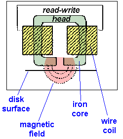
When current is passed through the write coil, the write head becomes magnetized and the magnetic flux links with the oxide film and causes to become magnetized in the region of the write gap. A current in the opposite direction would cause the induced magnetism to be of the opposite sense, these two states are used to represent binary 1 and 0. As the drum is rotated past the read head, the magnetic flux in the region on the recorded areas causes an e.m.f to be induced in the read coil.
The size and capacities of magnetic drum very greatly. Small drums with capacities less than 25,000 bits have 13 to 30 tracks and 15 to 60 heads. The speed of rotation varies from 120 R.P.M. to 75,000 R.P.M.
Magnetic Core Storage
Magnetic core memory consists of matrices of ferrite cores. These are in the form of small torpid of 0.4 to 0.8 mm diameter and of ferromagnetic material with a high degree of magnetic remenance (permanent magnetism). When a current is passed through the core, as shown in figure 8 a magnetic flux ϕ will be set up in the core in the direction shown. Because of the high remenance this flux will remain even after the current stops flowing. If we pass the current in the opposite direction the flux will be set up in the opposite direction as shown in figure 9. This way a 1 or a 0 can be stored by passing the current in one direction or another.
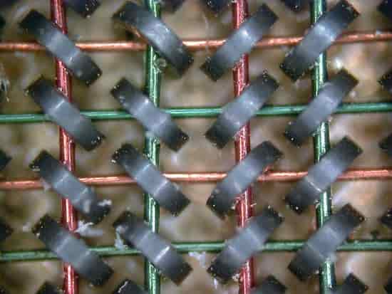
To read what is stored in the core, in addition on the original wire (known as drive winding) a second wire (the sense winding) is made to pass through the core. The current corresponding to storing of a 0 is passed through the drive winding. If a 1 was stored the flux will reverse and voltage will be induced in the sense winding.
The cores are grouped to form location, each information being a computer word. Such computer word is known as a byte and have a suitable size to store the data. The size of the word used depends upon the computer, but is generally in the range of 8 to 48 bits.
Core contains following four wires and these are placed in the core as shown in figure 9.
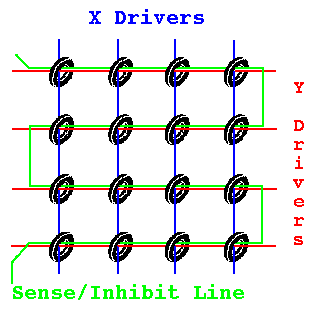
- X - drive wire
- Y - drive wire
- Z - inhibit wire
- Sense wire
In each matrix there is one inhibit wire and one sense or read wire, which pass through each core in the matrix.
Related Articles
Memories Semiconductor Memories
