RC Low-pass Filter Circuit
Fig. 1 shows the series RC LP circuit. This circuit is identical with that of high-pass circuit except for the fact that the output is now taken across capacitor C instead of across resistor R. However, the behavior totally differs from that of the high-pass circuit. As output is taken across the capacitor and reactance of a capacitor is inversely proportional to the frequency. The name low-pass circuit is because of the fact that it passes low frequencies readily but attenuates high frequencies. The attenuation of high frequency is due to the reactance of capacitor, which decreases with the increasing frequency. At very high frequencies, the capacitor acts as short circuit and therefore, the output drops to zero.

Sinusoidal Input
When a sinusoidal input Vi is applied to it, then the output Vo is given by:
![]()
Where
V0 is the output voltage
Vi is the input voltage
Xc is the capacitive reactance
R is the ohmic value of resistance
J is the imaginary axis of the complex plane.
Output is a frequency dependent quantity. At frequencies, —JXc << R. Under this condition, expression becomes almost zero i.e.
Vo = 0
At low frequencies, when –JXc >> R
Vo = Vi
Thus, low-pass circuit attenuates signals of high frequencies and do not affect signals of low frequencies. A frequency response curve of a low-pass circuit is shown in Fig. 1(b). The frequency at which the output becomes 70.7 percent of the input is called the cut-off frequency and is given by the expression.
fc = 1/2πRC
Step-Voltage Input:
For the step input of Fig. 2(a), the output voltage Vo,which is also voltage across capacitor C, rises exponentially towards the final value of V with a -lime constant RC. The output voltage Vo is given by:
Vo = V(1 – e-1/RC)

Fig. 2 (c) shows the response of low-pass RC circuit to a step input and the expression is valid only when the capacitor is initially fully discharged. If the capacitor was initially charged to a voltage Vo less than V, then the exponential charging equation would be:
Vo = V –(V – Vc)e-1/RC)
If this input step occurs at time t = t1, then.
![]()
Effects of the Circuit Time Constant on RC Low-pass:
The shape of the output waveform of an RC low-pass circuit depends upon the value of the circuit time constant T (as compared to pulse duration tp). For a pulse waveform of the low-pass circuit may be short, long or medium as compared to tp, the pulse duration of the input pulse wave.
Now let us considered, time period of the circuit T may be long when tp < 0.1T or short when tp > 10T or medium when T lies between the extremes, i.e., 10 T > tp > 0.1 T. The output waveforms are shown in Fig. 3

Observed that when circuit time constant T is very long; As compared to the pulse width tp the step input is converted to a ramp output. The low-pass circuit under such conditions behaves like and is sometimes called an integrator. It means, the output is the integral of the input waveform.
Low-pass Circuit as Integrator
Low-pass circuits also known as an integrator. The name low-pass circuit is designated because of the fact that the circuit pass low frequencies but attenuates high frequencies.
A circuit in which the output voltage is directly proportional to the integral of the input voltage is called an integrating circuit. Mathematically, the output voltage is given by:
output ∝ ∫ (input)
Vi ∝ ∫Vi dt
or
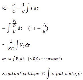
V =(1/ RC) ∫Vi dt
Where RC is a constant of proportionality
An integrating circuit is a simple RC series circuit with output taken across the capacitor C as shown in Fig. 4

In order to achieve a good integration, the following conditions must be satisfied.
- The time constant RC of the circuit should be very large as compared to the time period of the input signal.
- The value of R should be 10 or more times larger than X,.
Let Vi be the input alternating voltage and let i be the resulting alternating current. Since R is very large as compared to capacitive reactance Xc of the capacitor. It may be assume that voltage across R (i.e. VR) is equal to the input voltage, i.e.
Vi = VR
Now
I = VR/R = Vi/R
The charge q on the capacitor at any instant is:
Q =∫i dt
Output voltage is given by:
The output waveform from an integrating circuit depends upon the time constant and the shape of the input signal. Now let us consider some cases.
Input as a Square wave:
When input signal is a square wave and applied to an integrating circuit, the output will be a triangular wave as shown in Fig. 4. We know that integration means summation, therefore, output from an integrating circuit will be the sum of all the input signals at any instant. This sum is zero at point A and goes on increasing till it becomes maximum at point C. After this, the summation goes on decreasing to the on set of negative movements CD of the input signal.
Input as a Rectangular- Wave:
When input signalis a rectangular wave and applied to an integrating circuit, the output will be a saw-tooth wave as shown in Fig. 5. From point A signal goes on increasing till it becomes maximum at point C. After this, the summation goes on decreasing to the on set of negative movement CD of the input wave.

It means that the response of an integrating circuit to a rectangular wave is similar to that discussed for a square wave as discuss for square waver, except the output waveform, which is a sawtooth wave (instead of a triangular wave).
Applications:
Some important applications of an integrating circuit are given as under:
- To perform mathematical integration in analogue computers.
- To generate a triangular wave from a square wave.
- To generate a sawtooth wave from a rectangular wave.
- To trigger the electronics devices.