Three Phase to Six Phase Transformer
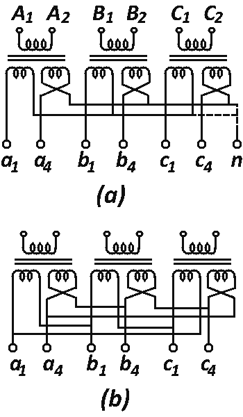
Three single phase transformers, each with one primary winding and identical secondary windings Or a three phase primary as in a three phase transformer with each phase having two identical secondary, can be interconnected to obtain six phase supply from a three phase source. The primaries can be connected in star or in delta and the secondaries as double star or double delta.

Figure 1. (a) Six Phase Connection (Double Star) (b) Six Phase Connection (Double Delta)
Three single phase two winding transformers can supply a six-phase load such as synchronous converter as shown in Fig. 2. Such connection is known as diametral. Three separate single phase low voltage distribution network can also be supplied form this connection. The secondaries are generally provided with mid-point tailings which can be connected with each other to form the earth connection.

Figure 2. Diametral Connection
Six phase supply is used in six phase machines such as six ring synchronous converter or a six-anode rectifier. Cooling Of Transformer
Cooling of Transformer
The energy lost in the transformer dissipates in the form of heat. In small transformers this energy is in small proportion of the total energy of the transformer. But this lost energy becomes quite greater in amount in transformers of higher kVA ratings. Like in other machines, this will affect the windings, insulation, etc. of the transformers. In some cases, short circuiting of points at which it is produced (i.e., windings and core) to the heat dissipating surfaces of the transformers.
Method of Cooling
Since there are no rotating parts which induce ventilating draught, transformers are more difficult to cool than rotating electrical machines.
For small transformers up to 20kVA, the external surface is sufficient to dissipate the heat by radiation. In large transformers additional means are provided for carrying away the heat. Transformers are classified in accordance with the meths d of insulating and cooling as follows:
Dry type:
In this method circulation of air takes place. Instruments transformers (except those for highest voltages) are ordinarily of dry type.
Oil Immersed Self-cooled:
The natural circulation of oil through the cooling ducts in the windings and core takes place. The heat is transferred to the heat dissipating surfaces.
Oil Immersed Forced-air-cooled:
In this method the core and oils are immersed in oil and the cooling is increased by forced air over the cooling surfaces. The air is forced over the exterior cooling surfaces by means of fans mounted external to the transformer.
Oil immersed water-cooled:
The coils are immersed in oil; the cooling being affected by the circulation of water through a coil installed in the transformer tank and immersed in oil.
Oil immersed forced oil-cooled:
In this method core and coils are immersed.
Air blast cooling:
This is a dry type cooling. Transformer is cooled by a forced circulation of air through the core and coils. In such case transformers are located over an air chamber in which the air is maintained under pressure by blowers. The air is forced up through the core and windings and is charged through the top of the case.
Transformer On Load
When transformers become warm, the oil and gas expand. The gas at the top of the oil is expelled. When the transformer cools, air is drawn into the transformer. Hence the transformer breathes. Moisture is drawn in during this process. This moisture is readily absorbed by the oil, and the dielectric properties of the oil are reduced. Moreover, the oxygen in contact with the oil oxidizes it, forming a thick sludge. This sludge adheres to the windings, clogging the oil ducts and sometimes resulting in burn outs. In small transformers up to 2,000 kVA, breathing may be prevented by sealing the core and case with a gasket and the bushings and leads with an insulating compound. In large transformers, this method becomes difficult. Hence an apparatus called breather is installed. Breather contains some dehydrating substances which finishes the chances of formation of explosive mixtures over the oil.
Another method for preventing the deterioration of the oil is to mount an expansion tank, or conservator on top of the transformer case. This tank is connected by pipe to the transformer and is always partly filled with oil. It absorbs the expansion and contraction of the oil so that the main transformer is always full and the surface of the oil is not exposed to oxygen. The conservator is provided w. a breather containing a drying agent such as calcium chloride.
