Understanding the Fundamental Role of Logic Gates in Digital Electronics
The digital landscape we inhabit today is the result of countless technological advances, leading to complex structures and entities. One crucial yet often overlooked component is logic gates. Which are considered the building blocks of digital electronics, can unlock a wealth of knowledge and equip you with an understanding of the foundation on which the digital realm thrives.
In straightforward terms, logic gates are simple electronic devices that manipulate one or more binary inputs to produce a single output. They are the physical example of binary logic, representing Boolean algebra laws and allowing for the execution of complex operations through simple actions.
This essay seeks to elucidate these fundamental entities, allowing the reader to delve into the world of digital electronics. It serves as an exploratory journey into the realm of seven basic logic gates: AND, OR, NOT, NAND, NOR, XOR, and XNOR, explaining their functions, influence, and diverse applications.
Comprehension of these gates is critical in digital electronics, a vital aspect of various fields such as Computer Science, Telecommunications, Information Technology, and Electrical Engineering. It not only provides a solid foundation for assimilating digital creation but also for understanding and troubleshooting digital systems, servers, and networks.
After reading this comprehensive guide, you will have gained insightful knowledge of this foundational aspect of digital electronics, armed with both theoretical knowledge and practical applications of these devices. So let us embark on this enlightening journey, peeling back the veil surrounding Logic Gates and their realm, one gate at a time.
Detailed Definition of Logic Gates
To fully grasp the operations and premise of digital electronics, it's indispensable to deep-dive into the distinctive attributes of logic gates.
Technical Terms
Step one on our journey revolves around immersing ourselves in the jargon, the specialized terminology that makes understanding easier and studying more insightful. Logic gates play a critical role in a series of domains such as Binary Logic Circuits, Digital Electronics Gates, Transistor-Transistor Logic Gates, and MOSFET Logic Gates, thus making it vital to comprehend these technical constructs. In the realm of digital electronics and network servers, the term 'Binary Logic Circuits' corresponds to a system where binary variables undergo logical operations, with the results propelling the actions derived from basic logic gates. 'Digital Electronics Gates' might sound similar but cater to a broader scale, as they embody electronic circuits performing logical operations on digital inputs. Moving one step forward, 'Transistor-Transistor Logic Gates' can be understood as BJT-based digital circuits at work. 'MOSFET Logic Gates' implements MOS technology in creating gates from a more complex playbook. These technical terms not only help in conceptualizing the science behind logic gates but also bridge the gap between theory and application, transforming our understanding of how digital networks operate.
Representation of Logic Gates
Any system or operation is incomplete without an appropriate representation, and digital electronics is no exception. This makes a symbolic representation of immense importance in this exploration. Scientifically accurate symbols transcribe the nature and functionality of logic gates into visual cues, supporting logic gate simplification and aiding in their comprehensive analysis. For instance, AND and OR Gates, the fundamentals of binary logic circuits, are represented by their distinct symbols, forming the foundation of electronic circuit gates. The essence of these symbols translates to actual electrical circuits. For example, the inputs and output of NAND and NOR gates are depicted in a symbolic notation that corresponds to their real circuit operations. Furthermore, the integration of these symbols portrays the structure of integrated circuit gates, creating a tangible connection between the abstract and the concrete. Understanding these symbols is essential for any aspiring digital enthusiast as they aid in analyzing complex circuits, contributing significantly to system troubleshooting and functioning.
Function of Logic Gates
At their core, logic gates function as digital electronics' heart, implementing Boolean algebra applications, and serving as the linchpin in the establishment of binary and combinational logic circuits. From executing primary operations in basic AND, OR, NAND, and NOR gates to carrying out XOR and XNOR operations, these gates fulfill broad aspects of all digital electronic applications. Real-world computing operations, like data storage, manipulation, processing, and data transfer, heavily rely on the fundamental operations executed by logic gates. The combined action of these gates in a digital system or circuit plays a significant role in generating inputs necessary for advanced digital tasks. This is the key to understanding the essence of digital logic: truth table analysis and the functioning of logic gates. In this context, we can say that the functioning of logic gates is not limited to theoretical importance but finds crucial application in real-world computing and digital electronics operations with vast implications. Overall, this in-depth exploration defines the primary components of logic gates, revealing their practical significance, theoretical relevance, and broader role in enabling our digital world.
Explanation of the Seven Basic Logic Gates
In any journey of understanding, one must comprehend the fundamental building blocks. In the context of digital electronics and logic gate operations, AND, OR, and NOT gates form the essence.
The AND Gate
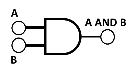
As a primary gate in binary logic circuits, the AND gate assumes a position of undeniable importance. Functionally, it runs on the basic rule that all inputs need to be "true" or "1" to result in a "true" or "1" output, reflecting a significant application of Boolean algebra. The symbolic representation of the AND gate is a simplistic D-shaped schematic that screams clarity and precision. This symbol, when decoded through a truth table, results in a straightforward correlation indicating that only when all inputs are high, the output will be high; in all other scenarios, the output will be low. Taking a practical example, consider a simple electronic system where the activation of all the switches is essential to turn on a specific light. In this situation, each switch can represent a binary input, and the light can represent the output. The activation of the entire system resembles an AND operation indicating a logical connection between practical applications and binary logic circuits.
| Input A | Input B | Output (A AND B) |
|---|---|---|
0 | 0 | 0 |
0 | 1 | 0 |
1 | 0 | 0 |
1 | 1 | 1 |
The OR Gate
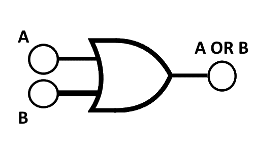
Next in line comes the OR gate, another primary component of digital electronics gates. Functionally, the OR gate operates on the basic rule that just one or more "true" or "1" inputs result in a “true” or “1” output. Symbolically, an OR gate is represented through a curvature-inspired design, simplistic and clear, that any student of digital electronics can understand. The truth table provides the means of analyzing it, making it evident that when any of the inputs are high, the output will be high. Practically speaking, consider a scenario where multiple switches independently control a specific light, representing binary inputs and a binary output, respectively. In this setting, the action of any single switch (or combination of switches) turning on the light exemplifies an OR operation, thereby solidifying the relation between digital electronic gates and practical applications.
| Input A | Input B | Output (A OR B) |
|---|---|---|
0 | 0 | 0 |
0 | 1 | 1 |
1 | 0 | 1 |
1 | 1 | 1 |
The NOT Gate
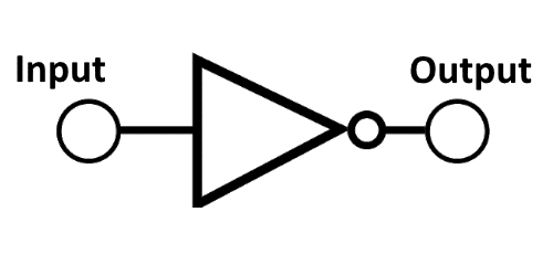
Closing on these fundamental gates, the NOT gate signifies one of the most uncomplicated yet influential logic gate functions. As a binary operator, it flips the binary input- a "true" or "1" input resulting in a "false" or "0" output, and vice versa. This inversing feature is why it's sometimes referred to as an inverter. Symbolically, the NOT gate is represented by a triangle followed by a circle, an emblem of its simple operation that completely inverts incoming binary signals. The truth table analysis hereby results in a simple but powerful rule of inversion. Taking an example from our everyday experiences, consider a simple electronic toggle switch; it's either on or off. When the switch is in the off position, the light (output) is off, and inversely when the switch is on, the light is on, reflecting a NOT operation. Understanding these basic gates paves the way for more complex operations and offers invigorating insights into the essence of digital electronics.
| Input | Output |
|---|---|
0 | 1 |
1 | 0 |
Working Mechanism for the Remaining Gates
After acquiring an understanding of the basic logic gates, it's time to delve into the functioning of the advanced counterparts, NAND, NOR, and XOR gates, that broaden the applications of digital electronics gates.
The NAND Gate
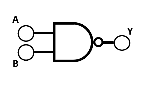
The NAND gate, synonymous with Not AND- a combination of NOT and AND gates, implements a unique function in binary logic circuits. Its working involves an AND operation followed by a NOT operation. Thus, the NAND gate operates by providing a "false" or "0" output only when all inputs are "true" or "1". Symbolizing a NAND gate requires incorporating the essence of an AND gate with an inversion circle, inducing a refrain from the AND operation. A truth table expounds this function, reiterating that a NAND gate results in a low output only when all inputs are high. Translating this operation into a practical example, consider a lighting system where the light remains on except when all the switches are on. This kind of operation is the realm of NAND gates, linking the theoretical functionality of logic gates with practical realms.
| Input A | Input B | Output Y |
|---|---|---|
0 | 0 | 1 |
0 | 1 | 1 |
1 | 0 | 1 |
1 | 1 | 0 |
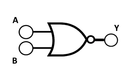
The NOR Gate
Next, we traverse onto a NOR gate, essential in electronic circuit gates, which flips the script on the OR gate. Therefore, a NOR gate provides a "true" or "1" output only when all inputs are "false" or "0". Its symbol is a depiction of an OR gate, harboring an inversion bubble, signifying the NOT-ness of the operation. The truth table gives us a fully unambiguous view into the operation of the NOR gate, clarifying that a "1" will only result when every input is "0". To visualize the NOR operation, imagine an alarm system controlled by multiple switches where the alarm is quiet only when all switches are off. This model system harnesses the operation of a NOR gate, creating an intersection between electronic gate circuits and everyday implementations.
| Input A | Input B | Output Y |
|---|---|---|
0 | 0 | 1 |
0 | 1 | 0 |
1 | 0 | 0 |
1 | 1 | 0 |
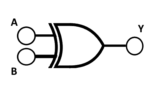
The XOR Gate
Lastly, we arrive at the XOR gate, a beautiful sample of integrated circuit gates, encapsulating "exclusive OR" functionality. In an XOR operation, the output is "true" or "1" if the inputs are not the same. The XOR gate's symbol features a distinct 'D' shape differentiating it from conventional OR and AND gates. An XOR truth table brings to light its unique functionality where the output is high only if the states of inputs are different. Envisioning the XOR functionality as a real-world scenario can be reflected in a system where two switches control a device, but only a single switch can be active at a time. Here, the XOR operation finds a perfect manifestation, beautifully showcasing how the XOR gate applies to practical contexts.
| Input A | Input B | Output Y |
|---|---|---|
0 | 0 | 0 |
0 | 1 | 1 |
1 | 0 | 1 |
1 | 1 | 0 |
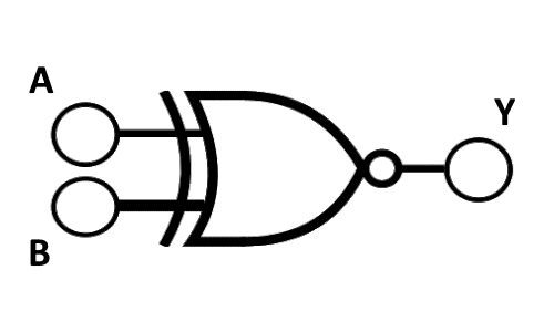
The XNOR Gate
XNOR is a digital logic gate with two inputs and one output. It performs an exclusive NOR operation, which means the output is HIGH (1) when both inputs are equal, either both 0 or both 1.
Input A | Input B | Output Y |
|---|---|---|
0 | 0 | 1 |
0 | 1 | 0 |
1 | 0 | 0 |
1 | 1 | 1 |
So, the output is 1 when both inputs are the same (either both 0 or both 1) and 0 when the inputs are different (one is 0 and the other is 1).
Wrapping Up the Intricacies of Logic Gates
Stepping back to take a comprehensive view, our exploration of logic gates has offered a journey from understanding basic notions to grasping the complex workings of these indispensable digital entities.
Summary of Key Points
This essay illuminated the integral role of logic gates in digital electronics, serving as the crucial building blocks in Binary Logic Circuits, Digital Electronics Gates, Transistor-Transistor Logic Gates, and MOSFET Logic Gates. Within this spectrum, technical terms enriched our understanding while the significance of symbolic representations was emphasized as they simplified our comprehension of complex circuits. Fundamentally, logic gates function to execute Boolean algebra applications - a fact demonstrated broadly through gate types like AND, OR, NOT, NAND, NOR, and XOR. These gates, each with their unique operations as elaborated through their respective truth tables analysis, not only facilitated our understanding of logic gate functions, but they also bridged the gap between theoretical knowledge and practical, real-world applications.
Final Thought
In the end, the impact of understanding logic gates stretches far beyond the realms of academia. These humble entities serve as the lifeblood of our digital era, where every device - from the simplest calculators to the most complex servers - relies on the functions of these gates. Given the era of fast-paced technological advances, the importance of understanding logic gates, their operations, and their practical implications can't be overstated. This essential knowledge enables us to delve deeper into the world of computing, potentially igniting innovation, accelerating problem-solving capabilities, and paving the way for future technological breakthroughs. Reflecting on this understanding and its implications, it’s clear that conquering the world of logic gates is not just about mastering the complex domains of digital electronics. It's about appraising how these concepts manifest in the technology we interact with every day. As we ponder upon the interweaving of Logic Gates in our lives, it adds a unique perspective, making us value the depths of these crucial components driving our modern digital civilization.