Transistor
Transistor is an three layer PNP or NPN semiconductor device with two junctions. Transistor is made from semiconductor materials i.e. Silicon, Germanium etc. Transistors have two basic types of applications: amplification and switching. In power electronics, where the main objective is the efficient control of power, transistors are invariably operated as switches. They are mainly used in chopper and inverter applications.
Diodes are uncontrollable switches having only two terminals. They only respond to switch the voltage across them. Transistors, on the other hand, have three terminals. two terminals act like switch contacts, while the third is used to turn the switch on and off. Thus, the control circuit can be independent of the circuit being controlled.
Transistors amplify current, for example they can be used to amplify the small output current from a logic chip so that it can operate a lamp, relay or other high current device. In many circuits a resistor is used to convert the changing current to a changing voltage, so the transistor is being used to amplify voltage.
A transistor may be used as a switch (either fully on with maximum current, or fully off with no current) and as an amplifier (always partly on).
The amount of current amplification is called the current gain, symbol hFE.
Types of transistor
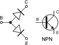
There are two types of standard transistors, NPN and PNP, with different circuit symbols. The letters refer to the layers of semiconductor material used to make the transistor. Most transistors used today are NPN because this is the easiest type to make from silicon. If you are new to electronics it is best to start by learning how to use NPN transistors.

The leads are labeled base (B), collector (C) and emitter (E). These terms refer to the internal operation of a transistor but they are not much help in understanding how a transistor is used, so just treat them as labels! In addition to standard (bipolar junction) transistors, there are field-effect transistors which are usually referred to as FETs. They have different circuit symbols and properties and they are not (yet) covered by this page.
Connecting Transistor
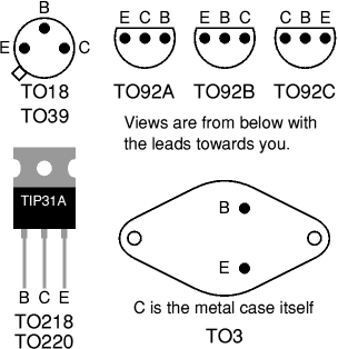
Transistors have three leads which must be connected the correct way round. Please take care with this because a wrongly connected transistor may be damaged instantly when you switch on. If you are lucky the orientation of the transistor will be clear from the PCB or stripboard layout diagram, otherwise you will need to refer to a supplier's catalogue to identify the leads. The drawings on the right show the leads for some of the most common case styles.
Please note that transistor lead diagrams show the view from below with the leads towards you. This is the opposite of IC (chip) pin diagrams which show the view from above.

Soldering Transistor
Transistors can be damaged by heat when soldering so if you are not an expert it is wise to use a heat sink clipped to the lead between the joint and the transistor body. A standard crocodile clip can be used as a heat sink.

Do not confuse this temporary heat sink with the permanent heat sink (described below) which may be required for a power transistor to prevent it overheating during operation.
.
Heat Sinks

Waste heat is produced in transistors due to the current flowing through them. Heat sinks are needed for power transistors because they pass large currents. If you find that a transistor is becoming too hot to touch it certainly needs a heat sink! The heat sink helps to dissipate (remove) the heat by transferring it to the surrounding air.
Testing a transistor
Transistors can be damaged by heat when soldering or by misuse in a circuit. If you suspect that a transistor may be damaged there are two easy ways to test it:

1. Testing with a multi-meter
Use a multimeter or a simple tester (battery, resistor and LED) to check each pair of leads for conduction. Set a digital multimeter to diode test and an analogue multimeter to a low resistance range.
Test each pair of leads both ways (six tests in total):
- The base-emitter (BE) junction should behave like a diode and conduct one way only.
- The base-collector (BC) junction should behave like a diode and conduct one way only.
- The collector-emitter (CE) should not conduct either way.
The diagram shows how the junctions behave in an NPN transistor. The diodes are reversed in a PNP transistor but the same test procedure can be used.
Device | Power (max) | Vds (max) | Id (max) |
|---|---|---|---|
| IRF710 | 36 Watts | 400 Volts | 2 Amperes |
| IRF510 | 40 Watts | 100 Volts | 5 Amperes |
| BUZ80A | 75 Watts | 800 Volts | 3 Amperes |
| IRF540 | 150 Watts | 100 Volts | 30 Amperes |
| IRFP260N | 300 Watts | 200 Volts | 50 Amperes |
| STE180NE10 | 360 Watts | 100 Volts | 180 Amperes |
2. Testing in a simple switching circuit
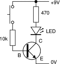
Connect the transistor into the circuit shown on the right which uses the transistor as a switch. The supply voltage is not critical, anything between 5 and 12V is suitable. This circuit can be quickly built on breadboard for example. Take care to include the 10kΩ resistor in the base connection or you will destroy the transistor as you test it!
If the transistor is OK the LED should light when the switch is pressed and not light when the switch is released. To test a PNP transistor use the same circuit but reverse the LED and the supply voltage.

