Telephone Set
The subscriber telephone set consists of the following parts:
- Microphone
- Receiver
- Switch connections to the telephone system
- Ringing circuitry
- Dial network
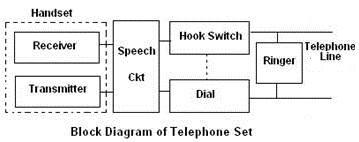
The instrument, which contains the microphone and the receiver, is called handset. The handset is placed on the cradle when the telephone is not in use. In this position it opens the switches and disconnects the handset from the telephone system. An electromagnet, called the ringer is connected to the telephone line on the exchange side, so that a ring can be received from the exchange when it is called. The exchange determines that whether the telephone is idle or busy or initiating a call by monitoring the dc current. A simplified circuit and Block diagram of the telephone set is shown in the figure.
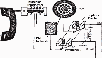
Circuit diagram of subscriber's telephone set
Telephone Set Transmitter
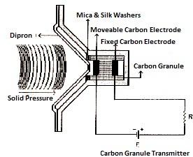
Microphone in telephony is regarded as transmitter. It is a transducer, which converts sound energy into electrical energy. There are different types of transmitters but carbon granules transmitter is the most widely used in the handset of the modern telephony. We will discuss the carbon granule transmitter only. It is based on the principle that the resistance of carbon granules is inversely proportional to pressure. The constructional details of the carbon transmitter, is illustrated in the figure.
It is the property of carbon that its resistance varies with pressure. The carbon transmitter does not produce any e.m.f. but only change its resistance with the changing pressure.
Carbon granules are placed between two electrodes in an insulated chamber. One electrode is fixed to the back of the chamber while the other electrode is attached with the movable diaphragm. The two electrodes are connected with the battery. The transmitter offers an electrical resistance to the flow of current, which is the resistance of the carbon granules. When the diaphragm moves inward and outward, due to sound pressure, the pressure on the carbon granules also changes. Thus the resistance of the carbon granules also varies with the changing pressure and hence the current flow between the two electrodes also varies. A current variation, corresponding to the sound pressure.
Telephone Set Receiver
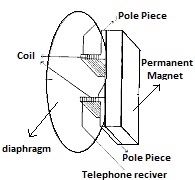
The sound reproducer in telephony is called receiver. The receiver does the reverse function of a transmitter. It is a device, which converts electrical energy into sound energy.The constructional details of the telephone receiver, is shown in the figure.
It consists of a diaphragm, permanent magnet and windings. When the incoming signal current passes through the windings, magnetic flux is produced. The magnetic flux follows the magnetic path, which consists of the iron path of the permanent magnet, the pole pieces, diaphragm and the two air gaps between the diaphragm and the pole pieces. Thus a varying magnetic pull is produced, which causes the diaphragm to vibrate in accordance with the signal current received and hence produce the sound. The permanent magnet is used to polarize the receiver. The pull on the diaphragm depends upon the magnetic flux density in the air gaps between the diaphragm and the pole pieces. Thus maximum change will be produced when the current changes in the coil.
Side Tone
When we speak in front of the telephone transmitter, .we hear our own voice in the receiver as a feedback. With the help of this feedback we are able to adjust the volume of our voice according to different situations. When the level of this feedback is high, we lower our voice and when it is low. we speak louder This feedback voice is called side tone.
Side tone may be defined as the reproduction of sound in the receiver picked up from the associated transmitter. Or the amount of voice power coupled from the transmitter to the receiver of the same telephone.
Too much side tone and complete absence of it is undesirable. In the former case, the speaker will keep his level of volume of voice very low and hence will affect the output of the transmitter. In the latter case, the telephone will-appear dead to the subscriber and this is a very uncomfortable feeling.
The desirable amount of side tone is that which we have in our daily free air conversation with each other across the table.
Antiside Tone Circuit
To control the level of the side tone to the desirable amount anti-side ton induction coil (A.S.T.I.C) is used in the subscriber's telephone set. The anti-side tone induction coil serves the following.
- Control the level of the side tone to the desirable amount.
- Ensures that no dc current flows through the receiver.
- Matching between the impedances of the transmitter and receiver with that of the line.
A simple circuit arrangement for the reduction of side tone is shown in the Figure.
The principle of the arrangement can be explained as follow.
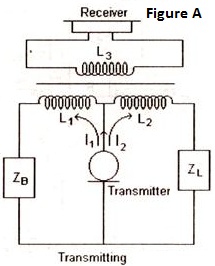
Consider the figure (A) in this case the transmitter is transmitting.If
Zb = Zi & L1 = L2
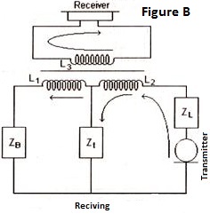
then the transmitter current divides equally in L1and L2. The magnetic field produced by these two windings will be equal and opposite and hence cancel each other's effect, thus no emf is induced in L1 and the side tone is completely eliminated. Practically L1and L2 are not exactly equal and hence some emf is induced in L1, thus the receiver receives a portion of transmitter current. In figure (B) the receiving current passes through LI and L2. the magnetic field produced are in the same direction and reinforced each other's effect. An emf is induced in the receiver circuit and current flows through the receiver.
The anti side tone circuit is modified to make it more Practical and this modified circuit is shown in the figure.
The tree windings L1, L2 and L3 are magnetically coupled. L1and L2 are not equal and hence an emf is induced in L3 from the transmitter. The value of R, across which the receiver is connected, is such that the voltage drop across it is equal and opposite to the emf induced in L3. This results in a much reduced side tone in the receiver.
Magneto Bell
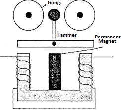
Bell is a means of signaling. When the calling party wants to call the called party. He must first give him a bell to draw his attention. For this purpose magneto bells used in the telephone set of each subscriber. The magneto bell works on AC supplied by the exchange. The constructional detail of the magneto bell is shown in the figure .It consists of a permanent magnet, two windings on the two legs of the iron yoke and an armature with a hammer. The static flux produced by the permanent magnet complete their path through the two parallel magnetic circuits. As the static field in each circuit is equal, thus the armature remains stationary. When alternating current flows through the windings, electromagnets are produced. The two fields interact with each other, supporting at one side and weakening at the other alternatively. The armature is attracted by the stronger magnetic field and the hammer strikes the gongs alternatively, thus produce a sound.
