Glucometer
Gluco-meter stands for Glucose meter. This instrument is used to check the % value of sugar in the blood of a human body.
Operation/ Working
It is a small digital meter with ON-OFF push button, screen indicate the readings, and a place to enter the blood soaked strip for testing the blood for sugar the different functions and readings of the result can be displayed on the screen. It can be give the result within a minute.

The Gluco Meter Consists of Following Parts
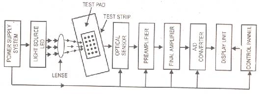
Power supply section
The power supply section of digital Gluco-meter consists of four or more alkaline manganese button batteries which are non dangerous or harmful. This section is used for providing necessary power to other stages.
Light source
There is a light source, which may be an LED with a lens. The light is focused on test strip with the help of lenses.
Test strip
There-are test strip, which is' shown in block diagram. This is used to obtain the sample of blood. Every strip has a test pad (filter) on it. This test pad has a certain chemical on it. The test strip is inserted in the test strip guide meter. A suspended drop of blood is allowed to from and is applied to the yellow test pad and without spreading the drop and without touching the pad. The test pad should be completely covered.
Due to the chemical on the test pad, the blood drop is divided into different particles separately.
Optical sensor
There is an optical sensor. The light from the light source is passed through the test pad. This light passes through the test pad counting the glucose or sugar particles.
When optical sensor receives this differentiated light, it produces potential according to the counting of glucose or sugar particles in blood. The potential (voltage) is a measure of glucose quantity.
Pre-amplifier
The signal produced by optical sensor is applied to a pre-amplifier, which performs pre-amplification of the signal.
Final amplifier
The output of pre-amplifier is applied to the final amplifier, which further amplifies the signal.
Analog to digital converter
The amplified analog signal is applied to an analog to digital converter (ADC), which converts it into digital form.
Display unit
The digital signal is applied to the display unit, which display the reading on screen.
Reading unit
Reading in milligram per deciliter (mg/de) or mille mole /liter.
Control panel unit
There is a control panel unit, which has different buttons for various options i.e. (button for ON & OFF)
Application
It is specially used in medical field to determine the quantity of sugar or Glucose in blood.
