Magnetic Amplifier
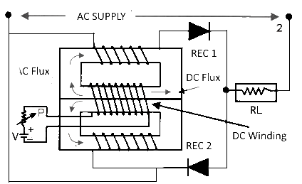
The diagram of magnetic amp or magnetic amplifier is shown in figure below, only silicon diodes are added in series with each winding of the saturated reactor. Magnetic amp made by addition rectifier. On upper core “A” current now can flow in the AC winding and through the load only when supply terminals are connected to point 2 current flows in the core “B” and only through the load. The load receives both the half cycles of alternating current but each core is magnetized by only half cycle of current.
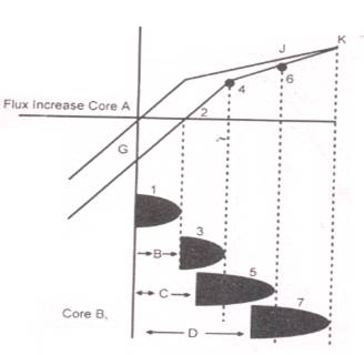
When AC power is 1st connected to the CKT, the current flows in the upper AC winding. It produces an initial current in core “A” as shown in figure (B). During the following half cycle this flux is not rest and some of its remaining part is blocked by the rectifier diode. The total mmf is increased by this amount through a small direct current has been added in A.C coil. From the AC supply the next half cycle combines with the flux “B” and raise the core flux to the point four and so on.


