Self Generated Transducers
The self-generated transducers don’t use an external power supply source. However, they provide an electrical output when stimulated by some physical form of energy. Transducers don’t use the external power supply source. However, they provide an electrical output when stimulated by some physical form of energy. The self-generated transducers are subdivided into many groups.
IC Temperature Transducer
The IC temperature Transducer uses a silicon chip as the sensing element. They are available in both voltage and current output configurations. The range of the IC sensors is limited below 200C°; they provide very linear changes in voltage or current change.
Advantages IC Temperature Transducer
There are some important advantages of the IC transducer over other type of transducers.
- Extremely Small in Physical size.
- Light in weight.Meager Cost.
- Suitable for small signal operation.
- Low Consumption.
- Easy to replace.
Dis-Advantages IC Transducer
- The temperature range is less than 200C°.
- Self-heating.
- An external Power supply is required.
- Slow operation.
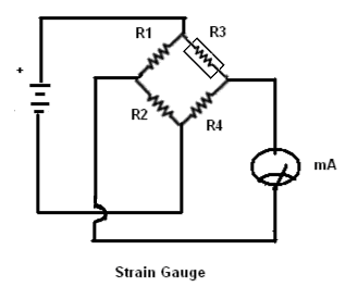
Strain Gauge
It is a passive transducer that converts a given strain to a resistance change. In other words, it utilizes resistance variation of the area to sense the difference in a strain produced by the force acting on the wire, It is used for the measurement of weight, Force, Pressure, etc. the force applied to the gauge causes band in wire, this bending action also changes the physical size of the gauge. The change in the size of the gauge produces a difference in the resistance change, this change is then fed to the bridge circuit which detects the small change in gauge resistance and then feeds it to the output device.
Hall-Effect Transducer
The Hall-effect Transducers are sensitive to magnetic field strength. The hall element is a small thin and flat slab of semiconductor material. When a current is passed through this slab and no magnetic field is present, zero output voltage is produced, when a magnetic field is brought near to the semiconductor of the Hall effect transducer, the current path is disturbed (Destroyed), and this Distortion causes the electron to flow through the right side of the material, which produces a voltage across the device as shown in the figure.
The hall–effect transducer is used for the measurement of speed, RPM, etc, of different motors and generators.


Thermo Couple Transducer
The thermocouple Transducer consists of two dissimilar metal wires joined at one end as shown in the given diagram, the end “A” is known as the “sensing junction”, and the other end is known as the “Cold” or “Reference” junction because it is kept at a low but a constant temperature (Reference Temperature) When end “A” is heated an e.m.f called thermo electric e.m.f in the Milli volt is produced between sensing junction”, and “Reference junction”. The magnitude of this e.m.f depends on the temperature difference between the hot and cold junctions and the type of wire material used, the thermocouples are made from several different materials covering a wide range of temperatures from -270C° to 2700C°.

They are available in simple wire form or in insulated wire form.
Uses of thermocouple
There are some uses for thermocouple transducers.
- Thermocouples are used to measure the temperature of the industrial furnaces
- They are suitable for very low temperatures.
- In medical fields, thermocouple probes are used for internal body temperature.
Piezo Electric Transducer
The production of Electric potential difference through mechanical pressure is called the piezoelectric phenomenon. It consists of crystals of ceramics such as barium titanate.

In the above figure, the crystal is pleased between a solid base and a force-sensing arm. When pressure is increased on the crystal's top surface, a potential difference is developed across its opposite ends connected to the output terminals. The output voltage found is directly proportional to the magnitude of the pressure. The potential difference develops in opposite polarity. If we apply a suitable AC voltage across the terminals of the crystal it starts vibration with its natural frequency which is very stable. The main disadvantage of this transducer is that it cannot measure static pressure.
Photo Conductive Cell (Light Transducer)
 The photoconductive cell is also called a photo-resistive device. It is based on the principle that the resistance of certain semiconductor materials decreases when they are exposed to light, in other words, such materials have high dark resistance.
The symbol for the photoconductive cell is shown in the figure, the photoconductive cell has a resistance of more than 100K it is also known as a cell. When it is exposed to the light, its resistance falls to a few ohms so this way the photoconductive cell is used as a light transducer.