Intel 8051 Microcontroller Addressing Modes
When instructions operate on data, the question arises: "Where are the data?" The answer to this question lies in the 8051's "addressing modes." There are several possible addressing modes and there are several possible answers to the question, such as "in byte 2 of the instruction," "in register R4," "in direct address 35H." or perhaps "in external data memory at the address contained in the data pointer."
Addressing modes are an integral part of each computers instruction set. They allow specifying the source or destination of data in different ways, depending on the programming situation. In this section, we'll examine all the 8051 addressing modes. There are eight modes available:
- Register Addressing
- Direct Addressing
- Indirect Addressing
- Immediate Addressing
- Relative Addressing
- Absolute Addressing
- Long Addressing
- Indexed Addressing
Register Addressing
The 8051 programmer has access to eight "working registers," numbered R0 through R7. Instructions using register addressing are encoded using the three least-significant bits of the instruction opcode to specify a register within this logical address space. Thus, a function code and operand address can be combined to form a short (1-byte) instruction.
The 8051 assembly language indicates register addressing with the symbol Rn where n is from 0 to 7. For example, to add the contents of Register 7 to the accumulator, the following instruction is used
ADD A, R7
and the opcode is 00101111B. The upper five bits, 00101, indicate the instruction, and the lower three bits, 111, the register.
There are four "banks" of working registers, but only one is active at a time. Physically, the register banks occupy the first 32 bytes of on-chip data RAM (addresses 00H-1FH) with PSW bits 4 and 3 determining the active bank. A hardware reset enables bank 0, but a different bank is selected by modifying PSW bits 4 and 3 accordingly. For example, the instruction
MOV PSW, #00011000B
activates register bank 3 by setting the register bank, select bits bits (RS1 and RSO) in PSW bit position 4 and 3.
Some instructions are specific to a certain register. Such as the accumulator, data pointer, etc. so addressing bits are not needed. The opcode itself indicates the register. These "register-specific" instructions refer to the accumulator as "A," the data pointer as "DPTR" the program counter as "PC," the carry flag as "C," and the accumulator-B register pair as "AB."For example,
INC DPTR
is a 1-byte instruction that adds to the 16-bit data-pointer.
Direct Addressing
Direct addressing can access any on-chip variable or hardware register. An additional byte is appended to the opcode specifying the location to be used. Depending on the high-order bit of the direct address, one of two on-chip memory spaces is selected. When bit 7 = 0, the direct address is between 0 and 127 (00H-7FH) and the 128 low-order on-chip RAM locations are referenced. All I/O ports and special function, control, or status registers, however, are assigned addresses between 128 and 255 80H—FFH). When the direct address byte is between these limits (bit 7 = 1), the corresponding special function register is accessed. For example, Ports 0 and 1 are assigned direct addresses 80H and 90H, respectively. It is usually not necessary to know the addresses of these registers; the assembler allows for and understands the mnemonic abbreviations "P0" for Port 0, "TMOD" for timer mode register, etc.). Some assemblers, such as Intel's ASM51, automatically include the definition of predefined symbols. Other assemblers may use a separate source file containing the definitions. As an example of direct addressing, the instruction
MOV P1 , A
transfers the content of the accumulator to Port 1. The direct address of Port 1 (9014) is determined by the assembler and inserted as byte 2 of the instruction. The source of the data, the accumulator, is specified implicitly in the opcode. The complete encoding of this instruction is
10001001 – 1st byte (opcode)
10010000 — 2nd byte (address of P1)
Indirect Addressing
How is a variable identified if its address is determined, computed, or modified while a program is running? This situation arises when manipulating sequential memory locations, indexed entries within tables in RAM, multiple-precision numbers, or character strings. Register or direct addressing cannot be used, since they require operand addresses to be known at assemble-time.
The 8051 solution is indirect addressing. RO and R1 may operate as "pointer" registers—their contents indicating an address in internal RAM where data are written or read. The least-significant bit of the instruction opcode determines which register (RO or RI) is used as the pointer.
In 8051 assembly language, indirect addressing is represented by a commercial "at" sign (@) preceding RO or R1. As an example, if R1 contains 40H and internal memory address 40H contains 55H, the instruction
MOV A, @R1
Moves 55H into the accumulator.
Indirect addressing is essential when stepping through sequential memory locations. For example. the following instruction sequence clears internal RAM from address 60H to 7F1-1:
MOV R0, #60H
LOOP: MOV @R0, #0
INC R0
CJNE R0, #80H, LOOP
(continue)
The first instruction initializes R0 with the starting address of the block of memory; the second instruction uses indirect addressing to move 00H to the location pointed at by R0; the third instruction increments the pointer (R0) to the next address; and the last instruction tests the pointer to see if the end of the block has been reached. The test uses 80H, rather than 7FH, because the increment occurs after the indirect move. This ensures the final location (7FH) is written to before terminating.
Immediate Addressing
When a source operand is a constant rather than a variable (i.e., the instruction uses a value known at assemble-time), then the constant can be incorporated into the instruction as a byte of "immediate" data. An additional instruction byte contains the value.
In assembly language, immediate operands are preceded by a number sign (#). The operand may be a numeric constant, a symbolic variable, or an arithmetic expression using constants, symbols, and operators. The assembler computes the value and substitutes the immediate data into the instruction. For example, the instruction
MOV A, #12
loads the value 12 (0CH) into the accumulator. (It is assumed the constant "12" is in decimal notation, since it is not followed by "H.")
With one exception, all instructions using immediate addressing use an 8-bit data constant for the immediate data. When initializing the data pointer, a 16-bit constant is required. For example,
MOV DPTR, #8000H
is a 3-byte instruction that loads the 16-bit constant 8000H into the data pointer.
Relative Addressing
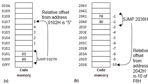
Relative addressing is used only with certain jump instructions. A relative address (or offset) is an 8-bit signed value, which is added to the program counter to form the address of the next instruction executed. Since an 8-bit signed offset is used, the range for jumping is —128 to +127 locations, The relative offset is appended to the instruction as an additional byte.
Prior to the addition, the program counter is incremented to the address following jump instruction; thus, the new address is relative to the next instruction, not the address of the jump instruction.
Normally, this detail is of no concern to the programmer, since jump destinations are usually specified as labels and the assembler determines the relative offset accordingly. For example, if the label THERE represents an instruction at location 1040H, and the instruction
SJMP THERE
is in memory at locations 1000H and 1001H, the assembler will assign a relative offset of 3EH as byte 2 of the instruction (1002H + 3EH = 1040H).
Relative addressing offers the advantage of providing position-independent code (since"absolute" addresses are not used). but the disadvantage that the jump destinations are limited in range.
Absolute Addressing
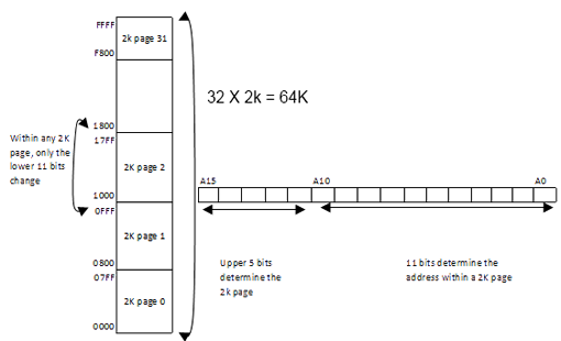
absolute addressing is used only with the ACALL and AJMP instructions. These 2-byte instructions allow within the current 2K page of code memory by providing the 11 least significant bits of the destination address in the opcode(A10-A8) and byte 2 of the instruction (A7 - A0).
The upper five bits of the destination address are the current upper five bits in the program counter, so the instruction following the branch instruction and the destination for the branch instruction must be with in the same 2K page,since A15 - A11 do not change. For example, if the label THERE represents an instruction at address 0F46H, and the instruction
AJMP THERE
is the memory location 0900H and 0901H. the assembler will encode the instruction as
11100001 - 1st byte (A10 - A8 + opcode)
01000110 - 2nd byte (A7 - A0)
The underlined bits are the low order 11 bits of the destination address, 0F46H = 0000111101000110B. The upper five bits in the program counter will not change when the instruction executes. Note that both the AJMP instruction and the destination are with in the 2K page bounded by 0800H and 0FFFH, and therefore have the upper five address bits in common.
Absolute addressing offers the advantage of short (2-byte) instructions, but has the disadvantage of limiting the range for the destination and providing position dependent code.
Long Addressing
Long addressing is used only with the LCALL and LJMP instructions. These 3-byte instructions The advantage include a full 16-bit destination address as bytes 2 and 3 of the instruction.
The advantage is that the full 64K code space may be used, but the disadvantage is that the instructions are three bytes long and are position-dependent. Position-dependence is a disadvantage because the program cannot execute at different addresses. If, for example, a program begins at 2000H and an instruction such as LJMP 2040H appears, then the program cannot be moved to, say, 4000H. The LJMP instruction would still jump to 2040H, which is not the correct location after the program has been moved.
Indexed Addressing
Indexed addressing uses a base register (either the program counter or the data pointer) and an offset (the accumulator) in forming the effective address for a JMP or MOVC instruction. Jump tables or lookup tables are easily created using indexed addressing.