Intel 8086/8088 Microprocessor
The 8086 microprocessor is available with clock frequency of 5, 8 and 10 megahertz. It is an Intel microprocessor and also a 16 bit microprocessor. It means that its ALU, internal register and most of the instructions are designed so that these can work on the 16 bit memory word. The main characteristics of 8086 microprocessor are as follows
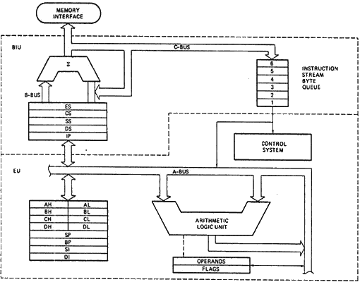
Block Diagram
Data Bus 16 bit
Address Bus 20 bit
Memory 1 MB
Instructions 25 Million/Sec or 1 instruction in 400 Nano second
The 8086 microprocessor has two sections that are E.U and BIU.
E.U Execution Unit
E.U unit performs the following functions.
- It performs the logic and arithmetic operation on memory or register.
- It receives the instruction from prefetch queue and decodes it.
- It stores the information temporary in the register array.
The execution unit consists of register array unit ALU and CU instruction pointer unit. The register array unit stores the data or information or instructions temporary. This unit consists of many registers which stores the data.
The ALU and CU perform the mathematical and logical operations on the data and also control all the functions of the execution and bus interface unit.
Parts of E.U
- Control Circuit
- Instruction Decoder
- ALU
- General Purpose Register
- Special Purpose Register
Control Circuit
The control circuit controls all the operations and flow of data inside the microprocessor.
Instruction Decoder
The instruction decoder works to translate or decode the instructions which are fetched from the memory. After translation it places the instructions in a series to perform the required task.
ALU
This is a 16 bit unit which performs the AND, OR, Exclusive, Addition, Subtraction, Increment, Decrement, Complement and Shift functions.
General Purpose Registers
The EU has 8 general purpose registers. Which are named as AL, AH, BL, BH, CL, CH, DL, and DH these are all 8 bit registers but these can also be used as 16 bit registers, when we take the different pairs of these registers. The possible pairs are
AL, AH = Ax
BL, BH = Bx
CL, CH = Cx
DL, DH = Dx
AL register is also called accumulator because it has some characteristics different from other general purpose registers.
Special Purpose Registers
The 8086 microprocessor has a 16 bit register for flag register. In this register 9 bits are active for flags. This register has 9 flags which are divided into two parts that are as follows

Conditional Flags
Conditional flags represent result of last arithmetic or logical instruction executed. Conditional flags are as follows:
- CF (Carry Flag)
This flag indicates an overflow condition for unsigned integer arithmetic. It is also used in multiple-precision arithmetic.
- AF (Auxiliary Flag)
If an operation performed in ALU generates a carry/barrow from lower nibble (i.e. D0 – D3) to upper nibble (i.e. D4 – D7), the AF flag is set i.e. carry given by D3 bit to D4 is AF flag. This is not a general-purpose flag; it is used internally by the processor to perform Binary to BCD conversion.
- PF (Parity Flag)
This flag is used to indicate the parity of result. If lower order 8-bits of the result contains even number of 1’s, the Parity Flag is set and for odd number of 1’s, the Parity Flag is reset.
- ZF (Zero Flag)
It is set; if the result of arithmetic or logical operation is zero else it is reset.
- SF (Sign Flag)
In sign magnitude format the sign of number is indicated by MSB bit. If the result of operation is negative, sign flag is set.
- OF (Overflow Flag)
This stands for over flow flag. It occurs when signed numbers are added or subtracted. An OF indicates that the result has exceeded the capacity of machine. It becomes set if the sign result cannot express within the number of bites.
Control Flags
Control flags are set or reset deliberately to control the operations of the execution unit. Control flags are as follows:
- TF (Trap Flag):
It is used for single step control. It allows user to execute one instruction of a program at a time for debugging. When trap flag is set, program can be run in single step mode.
- IF (Interrupt Flag):
It is an interrupt enable/disable flag. This stands for interrupt flag. This flag is used to enable or disable the interrupt in a program. If it is set, the maskable interrupt of 8086 is enabled and if it is reset, the interrupt is disabled. It can be set by executing instruction sit and can be cleared by executing CLI instruction.
- DF (Direction Flag):
This flag stands for direction flag and is used for the direction of strings. If it is set, string bytes are accessed from higher memory address to lower memory address. When it is reset, the string bytes are accessed from lower memory address to higher memory address.