Bistable Multivibrator
The bistable multivibrator has two absolutely stable states. It will remain in whichever state it happens to be until a trigger pulse causes it to switch to the other state. For instance, suppose at any particular instant, transistor Q1 is conducting and transistor Q2 is at cut-off. If left to itself, the bistable multivibrator will stay in this position forever. However, if an external pulse is applied to the circuit in such a way that Q1 is cut off and Q2 is turned on, the circuit will stay in the new position. Another trigger pulse is then required to switch the circuit back to its original state.
In other words, a multivibrator that has both the state stable is called a bistable multivibrator. It is also called a flip-flop, trigger circuit, or binary. The output pulse is obtained when, and why a driving (triggering) pulse is applied to the input. A full cycle of output is produced for every two triggering pulses of correct polarity and amplitude.
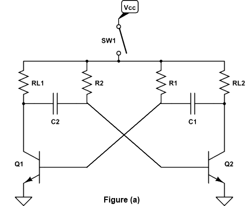
Figure (a) shows the circuit of a bistable multivibrator using two NPN transistors. Here the output of a transistor Q2 is coupled put of a transistor Q1 through a resistor R2. Similarly, the output of transistor Q1 is coupled to the base of transistor Q2 through a resistor R1. The capacitors C2 and C1 are known as speed-up capacitors. Their function is to increase the speed of the circuit in making an abrupt transition from one stable state to another stable state. The base resistors (R3 and R4) of both transistors are connected to a common source (-VBB). The output of a bistable multivibrator is available at the collector terminal of both the transistor Q1 and Q2. However, the two outputs are the complements of each other.

Let us suppose that Q1 is conducting, then the fact that point A is at nearly ON makes the base of Q2 negative (by the potential divider R2 - R4) and holds Q2 off.
Similarly, with Q2 OFF, the potential divider from VCC to -VBB (RL2, R1, R3) is designed to keep the base of Q1 at about 0.7V ensuring that Q1 conducts. It is seen that Q1 holds Q2 OFF and Q2 holds Q1 ON.
Suppose, now a positive pulse is applied momentarily to R. It will cause Q2 to conduct. As the collector of Q2 falls to zero, it cuts Q1 OFF, and consequently, the BMV switches over to its other state.
Similarly, a positive trigger pulse applied to S will switch the BMV back to its original state.
Uses:
- In timing circuits as the frequency dividers
- In counting circuits
- In computer memory circuits
Bistable Multivibrator Triggering
To change the stable state of the binary it is necessary to apply an appropriate pulse in the circuit, which will try to bring both the transistors to the active region and the resulting regenerative feedback will result in the change of state.
Triggering may be of two following types:
- Asymmetrical triggering
- Symmetrical triggering
(I) Asymmetrical triggering
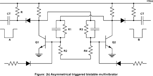
In asymmetrical triggering, there are two trigger inputs for the transistors Q1 and Q2. Each trigger input is derived from a separate triggering source. To induce transition among the stable states, let us say that initially the trigger is applied to the bistable. For the next transition, now the identical trigger must appear at the transistor Q2. Thus it can be said that the asymmetrical triggering of the trigger pulses derived from two separate sources and connected to the two transistors Q1 and Q2 individually, sequentially change the state of the bistable.
Figure (b) shows the circuit diagram of an asymmetrically triggered bistable multivibrator.

Initially, Q1 is OFF and transistor Q2 is ON. The first pulse derived from the trigger source A, applied to the terminal turn it OFF by bringing it from the saturation region to active transistor Q1 is ON and transistor Q2 is OFF. Any further pulse next time then the trigger pulse is applied at terminal B, the change of stable state will result with transistor Q2 On and transistor Q1 OFF.
Asymmetrical triggering finds its application in the generation of a gating waveform, the duration of which is controlled by any two independent events occurring at different time instants. Thus measurement of the time interval is facilitated.
(II) Symmetrical Triggering
There are various symmetrical triggering methods called symmetrical collector triggering, symmetrical base triggering, and symmetrical hybrid triggering. Here we would like to explain only symmetrical base triggering (positive pulse) only as given under symmetrical Base Triggering.
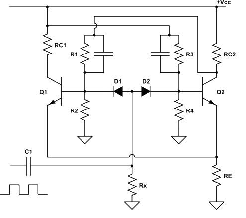
Figure (c) shows the circuit diagram of a binary with a symmetrical base triggering applying a positive trigger pulse.

Diodes D1 and D2 are steering diodes. Here are the positive pulses, try to turn the ON and OFF transistors. Thus when transistor Q1 is OFF and transistor Q2 is ON, the respective base voltages and VB1N, OFF and VB2N, ON. It will be seen that VB1N, OFF > VB1N, ON. Thus diode D2 is more reverse-biased compared to diode D1.
When the positive differentiated pulse of amplitude greater than (VB1N, OFF + Vɣ) appears, the diode D1 gets forward biased, transistor Q1 enters the active region and with subsequent regenerative feedback Q1 gets ON, and transistor Q2 becomes OFF. On the arrival of the next trigger pulse now the diode D2 will be forward biased and ultimately with regenerative feedback it will be in the ON state.
Applications of Bistable Multivibrator
A bistable multivibrator, also known as a flip-flop circuit, is a fundamental digital electronic circuit that has two stable states and is commonly used in various applications for storing and processing binary information. Here are some of the key applications of bistable multivibrators:
- Memory Elements: Bistable multivibrators are frequently used as memory elements in digital circuits. They can store a single bit of information (0 or 1) and maintain it until explicitly changed. This is the basis for creating sequential logic circuits and registers.
- Latch Circuits: Bistable multivibrators are used to create latch circuits, which are essential building blocks in digital systems. Latches can temporarily hold and retain data until a control signal triggers a change in state.
- Flip-Flops: Bistable multivibrators are the foundation of flip-flop circuits, which are used to build memory cells, registers, counters, and various sequential logic circuits in digital systems. Different types of flip-flops, such as D flip-flops, JK flip-flops, and T flip-flops, are derived from bistable multivibrator configurations.
- Counters: Bistable multivibrators play a crucial role in creating digital counters. By connecting multiple flip-flops in a specific configuration, you can create binary counters that can count events or cycles.
- Register Circuits: Bistable multivibrators are used to build registers, which are used for temporarily storing data in digital systems. Registers are commonly used in microprocessors for various operations such as arithmetic, logic, and data movement.
- Clock Divider Circuits: Bistable multivibrators can be used in clock divider circuits to generate lower-frequency clock signals from a higher-frequency clock source. This is useful in designing circuits that require different clock frequencies for different sections.
- State Machines: Bistable multivibrators are integral components in creating finite state machines (FSMs) or state registers. These are used in digital systems for tasks like control, sequencing, and protocol handling.
- Synchronization: Bistable multivibrators are employed for synchronization purposes in digital circuits. They can be used to synchronize data transfers, ensuring that signals arrive at the correct time and avoid issues like data corruption or metastability.
- Digital Timing: Bistable multivibrators are used to generate precise timing signals, such as clock signals for synchronous systems. They contribute to proper synchronization and timing coordination in digital circuits.
- Logic Level Conversion: Bistable multivibrators can be used to convert logic levels, especially when interfacing between different logic families or voltage levels.
- Debouncing Switches: In certain cases, bistable multivibrators can be employed to debounce mechanical switches or buttons, ensuring that only a single stable state is registered for each press.
- Frequency Division and Modulation: Bistable multivibrators can be used in frequency division and modulation circuits, where they help create specific frequency patterns or control signal modulation.
In essence, bistable multivibrators serve as essential building blocks in digital electronics, forming the basis for memory storage, sequential logic, counters, and other key functions in a wide range of digital systems and applications.
Advantages of Bistable Multivibrator:
- Digital Memory Storage: Bistable multivibrators provide a stable means of storing digital information (0 or 1), forming the basis for memory cells and sequential logic circuits.
- Simple Circuitry: Bistable multivibrators can be implemented with a relatively small number of components, making them straightforward to design and integrate into digital systems.
- Versatility: They are fundamental building blocks that can be combined to create more complex digital circuits like counters, registers, and flip-flops, catering to a wide range of applications.
- Instantaneous Response: Bistable multivibrators switch between states almost instantaneously when triggered, making them suitable for applications requiring fast state changes.
- Low Power Consumption: Since they maintain their states without continuous power consumption, bistable multivibrators are energy-efficient for storing and maintaining binary data.
- Digital Noise Immunity: Bistable circuits are inherently immune to noise and signal fluctuations in the input because they operate based on well-defined voltage thresholds.
- Digital Signal Processing: They serve as basic building blocks for digital signal processing, logic manipulation, and memory functions in microcontrollers and microprocessors.
Disadvantages of Bistable Multivibrator:
- Lack of Analog Behavior: Bistable multivibrators are primarily suited for digital applications and are not well-suited for continuous analog signal processing.
- Finite States: They have only two stable states (binary), limiting their application in systems requiring multiple states or analog-like behavior.
- Potential Metastability: During state transitions, bistable multivibrators can experience a brief period of instability called metastability, which can result in erroneous behavior if not handled properly.
- Limited Functionality: Bistable multivibrators have a specific function of storing binary information, so they are not suitable for tasks requiring complex mathematical or continuous processing.
- Complex Designs for Advanced Functions: While basic bistable circuits are simple, more advanced functions (such as frequency division) might require more complex configurations.
- Propagation Delays: The propagation delay through a bistable multivibrator can introduce timing issues in certain applications where precise timing is critical.
- Timing Dependencies: The operation of bistable multivibrators depends on the timing of input signals and clock pulses, making them sensitive to variations in timing.
- Trigger Sensitivity: Bistable multivibrators can be sensitive to noise and variations in input signal quality, necessitating proper conditioning of input signals.
- Limited Analog-to-Digital Conversion: While they can store binary digital information, bistable circuits are not directly suitable for analog-to-digital conversion tasks.
- Configurational Complexity: Although the basic concept is simple, configuring bistable multivibrators for specific tasks might require careful component selection and circuit adjustments.
In summary, bistable multivibrators are foundational components in digital electronics, offering advantages such as memory storage, simplicity, and versatility. However, they have limitations related to their binary nature, lack of analog capabilities, and potential issues like metastability and timing dependencies. These factors should be considered when choosing their application and integrating them into digital systems.
