Decoder & Encoder
Decoder
Decoder is a circuit which converts the digital signal into analog signal. Its input will be in digital form while the output will be a continuous sine wave or analog wave.
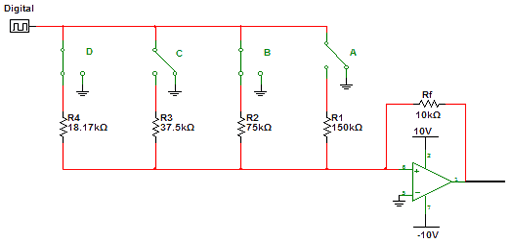
Decoder Circuit Diagram

D | C | B | A | output |
|---|---|---|---|---|
0 | 0 | 0 | 0 | 0.0 V |
0 | 0 | 0 | 1 | 0.2 V |
0 | 0 | 1 | 0 | 0.4 V |
0 | 0 | 1 | 1 | 0.6 V |
0 | 1 | 0 | 0 | 0.8 V |
0 | 1 | 0 | 1 | 1.0 V |
0 | 1 | 1 | 0 | 1.2 V |
0 | 1 | 1 | 1 | 1.4 V |
1 | 0 | 0 | 0 | 1.6 V |
1 | 0 | 0 | 1 | 1.8 V |
1 | 0 | 1 | 0 | 2.0 V |
1 | 0 | 1 | 1 | 2.2 V |
1 | 1 | 0 | 0 | 2.4 V |
1 | 1 | 0 | 1 | 2.6 V |
1 | 1 | 1 | 0 | 2.8 V |
1 | 1 | 1 | 1 | 3.0 V |
Explanation
As shown in the given diagram there are four resistances connected to the input of the amplifier through switches. Whenever, the input bite is one the switch is closed while it is open for zero bite. The ouput is given by
Output = gain X input
While
Gain = Rf/Rin
Where the value of Rf = 1 0 1 0
And is constant while the Rin is the input resistances which changes every time according to the input bites. The value of Rin depends upon the number of switches closed.
If the input is the input resistance Rn becomes 75 K parallel to 150 K. this is because switches A and B are closed while C and D are open.
Rin = 75 K // 150 K
= 10,000/50,000
= 0.2 X 3
=0.6 V
This is the prove for the truth table for the line 4
Encoder
Encoder is a circuit which converts the analog signal in to the digital signal.
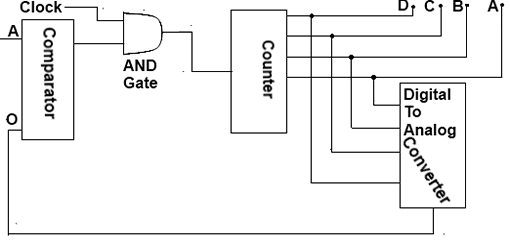
Encoder Circuit Diagram

Input | A | B | C | D |
|---|---|---|---|---|
0.0 V | 0 | 0 | 0 | 0 |
0.2 V | 1 | 0 | 0 | 0 |
0.4 V | 0 | 1 | 0 | 0 |
0.6 V | 1 | 1 | 0 | 0 |
0.8 V | 0 | 0 | 1 | 0 |
1.0 V | 1 | 0 | 1 | 0 |
1.2 V | 0 | 1 | 1 | 0 |
1.4 V | 1 | 1 | 1 | 0 |
1.6 V | 0 | 0 | 0 | 1 |
1.8 V | 1 | 0 | 0 | 1 |
2.0 V | 0 | 1 | 0 | 1 |
2.2 V | 1 | 1 | 0 | 1 |
2.4 V | 0 | 0 | 1 | 1 |
2.6 V | 1 | 0 | 1 | 1 |
2.8 V | 0 | 1 | 1 | 1 |
3.0 V | 1 | 1 | 1 | 1 |
The above circuit consists of the following parts.
Comparator
It is used to compare the two input values. If A is greater than B the output will be one. Otherwise it will be zero.
Counter
It is an electronic device which counts the number in binary system. It increases by one number whenever high input pulse is given.
AND Gate
The output of the AND gate is given to the counter which becomes the pulse for it. This pulse is high whenever the output of the AND gate is one.
Digital to Analog Converter
The output of the counter is given to digital converter which produces analog output and is given to comparator.
Operation of Encoder Circuit
When input A is set it means that the counter is instructed to count up to that level at that time the counter output is 0000. As a result the B signal is 0 volt. The comparator compare A and B signals. As A is greater than B so the output of the comparator is one. This input signal is given to the counter which counts the next number. This is converted to analog signal which is again less than three volt and the same process continuous till the B signal is equal or becomes high then A.
