Delay Lines
In many pulse circuit applications, it is necessary to delay a signal a certain amount of time called delay time. Delay circuits may be classified in two main groups: electronic circuits (e.g. mono stable multi vibrator and blocking oscillator etc.) and electromagnetic delay lines.
The electronic circuit. operate on the principle of being in a stable until triggered by a pulse. Then they shift to a quasi stable state for a period of time determined usually by the time constant or RC circuit. After this period of time, the circuit returns against to its stable state until triggered again by another pulse. If some means is provided to have a pulse generated at a time the circuit returns to its stable state, a time delay circuit results. The output pulse is not necessarily an exact reproduction of the input pulse. Its amplitude and width are dependent upon the circuit producing it and not on the amplitude and width of the input pulse.

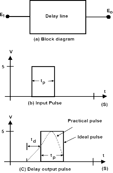
A delay line is required to delay a pulse for predetermined period of time constant distorting it. The block input to it is shown in figure 1 (a). The pulse input to it is shown in the figure 1 (b). The output is shown in figure 1 (c) observed that the delay line simply delays to input pulse by time td as shown in figure 1 (c).
Types of Delay Lines
There are two types of delay lines used in switching circuits the electronic types and electromagnetic type.
Electromagnetic Delay Lines
Electromagnetic delay lines may be further classified as distributed parameter or lumped parameter delay lines. The distributed parameter line more closely approaches a transmission line, whereas the lumped parameter line resembles a filter. Delay ranging from a few nanoseconds to hundreds of micro-seconds are obtainable with electromagnetic lines. For longer delays acoustic delay lines and storage devices are used. Acoustic delay lines employ acoustic wave propagation and electro-mechanical transducers at the input and output.
Among the common applications for electromagnetic delay lines are air navigation system such as DME (distance measuring equipment) using electrical information related to time. A cathode ray oscilloscope for observing fast waveforms may also use a electromagnetic delay line to delay the input signal to the vertical plates until the sweep is started. If the delay line were not included, the initial portion of the waveform might not be visible on the scope face. Other applications of delay line occur in distributed amplifiers, in pulse coders and decoders, in precise time measurement, in television and in digital computer systems.
Lumped Parameter Delay Lines
In its simplest form the lumped parameter consist of a number of inductors and capacitors are similar in value. The inductors are connected in series and the capacitors are connected through the junction between the inductors to the ground. Lumped parameter delay lines can be tapped at several points to give a series of delay and this property is useful i many applications. The products are of the order of 0.01 to 100,000 µ sec. In addition, lumped parameter delay lines are used as pulse forming networks (PFN) is such applications as radar modulators.

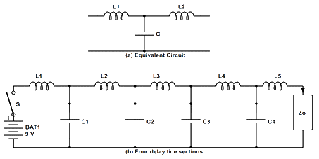
Figure 2 shows an equivalent circuit of the loss less transmission line. In such a circuit C is inter-conductor capacitance and L is the total equivalent inductance figure 2 shows the transmission lie divided into several equal lengths. A step input applied at Vi takes a certain finite time td to read the load Z0 td is called the delay time.
Let us consider the circuit of figure 2 as the step input is applied, capacitor C1start charging through (L1/2). When C1 gets completely charged, C2 starts charging. After C2 has charged C3 starts charging, and so on. Hence the pulse reaches Z0 after all the capacitors have been charged. The time that the total capacitance required to fully charged is the delay time td. Suppose the constant current I0 is following from the source Vi when capacitors C1,C2, C3 and so on are being charged then.
I0 = Vi/Zi
Where I0 is the constant current that flows from the input source which capacitance is being charged. Ei is the amplitude of the step voltage V and Zi is the input impedance of the lumped parameter delay lines measured in ohm.
If the load Zi become equal to the input impedance Zi then the load current will also be I0 after the pulse has reached at the load. Under such condition, there will be a constant current drain equal to I0 from the source V first charging the capacitance and then flowing through the load. In such a case, Z0 is called as characteristic impedance of the delay line. It is true that the characteristic impedance Z0 of transmission line is equal to its input impedance when the line is infinitely ling. It is the property of Z0 that a delay line is terminated in its characteristics impedance to save from the reflections or line oscillation.
For the lumped parameter delay line shown in figure 2 the characteristic impedance is
Where Z0 is the characteristic impedance, L is the inductance, C is the capacitance, td is the delay time of fc is the upper cut off frequency.
The circuit shown in figure 2 (a) is low pass equivalent circuit. It attenuates signals that have frequencies above upper cut off frequency fc.
Distributed Parameter Delay Lines
A transmission line may be conductive that serves to guide energy from one point (input) to another (output). Normally the transmission lines consists of pair of straight conducting wires or coaxial cables. Any linear conductor possesses both inductive and resistance.
Distributed parameter delay line are shown in figure figure 3. In a two wire transmission line the two wires are separated by a dielectric and therefore, distributed capacitance is also present. Because no capacitor is perfect, a dielectric leakage resistance must also be considered. The equivalent circuit for a short length of line, therefore must include all these elements with resistance R and inductance L in series, and dielectric leakage conductance G and capacitive reactance in shunt. A long line may be considered as made up a number of similar sections distributed along the length of the line. A transmission line is termed loss less or distortion less if
R = G = 0
Loss less lines are performed as delay lines because they do not introduce attenuation to the impressed signal. Further infinite lines are simulated by finite lines terminated in its characteristic impedance Z0.
The characteristics impedance of the line also depends on L and C and is given by:
The L and C of a transmission line are both functions of the geometry of the cross-section of the line. For example, a two wire transmission line made up of wires diameter d, which are separated by a distance of D (measured between wire centers), will have an inductance and capacitance given by:
Where ϵr is the relative dielectric constant.
For air ϵr = subtracting equation 2 in equation 3 and 4 we have.
Observe that the time delay is independent of the diameter of the spacing between them. In fact the time delay depends only upon the magnetic permeability (µ) and dielectric constant (ϵ) of the insulating material between the conductors.
Since
For a coaxial transmission line with linear inner conductor of radius d, outer conductor with diameter D, and the insulating material with relative dielectric constant ϵr,
Which is the same as for the two-wire transmission line. Electronics delay line is an electronic circuit used to delay a pulse waveform. Any mono-stable circuit may be used for this purpose. The input pulse is used to trigger the mono-stable circuit. The output is generated by the mono-stable circuit itself. The amplitude and duration tp of the output pulse is controlled by the mono-stable circuits. Hence, a mono-stable circuit can be used as pulse delay device as well as a pulse reshaping device. The most popularly used circuit as an electronic delay line is the monostable multivibrator. In such a case, the pulse must be delayed for one-bit at a time, which is equal to the pulse width time tp. An edge-triggered monostable multivibrator can be used for this purpose. The monostable multivibrator should be triggered by the negative going edge of the input pulse. Consider a monostable multivibrator circuit shown in figure 4 is being used as a delay circuit. The negative going edge turns the transistor Q1 OFF, the normally ON transistor at the same time voltage at Vo changes from VCE (ON) to VCC. It stay at VCC depends upon the time constant C1R1. If pulse width time tp1 become equal to tp2 and amplitude of both input and output pulses also become equal, then the pulse become delay by (one bit time) time tp. Delay lines are used in distributed amplifiers, cathode ray oscilloscope pulse coder and decoder, measuring instrument, Radar, T.V. system and computers.Electronic Delay Line
Mono-stable Multivibrator as a Time Delay Device
Uses of Delay Lines
