Monostable Multivibrators
In a monostable multivibrator, one of the state is absolutely permanent i.e, stable and the other one is temporary i.e, quasi-stable. When an external trigger pulse is applied to the mono-stable at appropriate point, the mono-stable changes it state from stabe state to quasi-stable state. It stays in the quasi-stable state for a predetermined length of certain interval remains there until another pulse is applied. Thus a mono stable multivibrator can not generate square wave of its own like an astable multivibrator. Only external pulse will cause if to generate the square wave.
In other words, a multi vibrator in which one transistor is always conducting (i.e. in the ON state) and the other is non conducting (i.e. in the OFF state) is called mono stable multivibrator. It is also called a single shot or single swing or a one shot multi vibrator. Other names are delay multi-vibrator and univibrator.
Here we like to describe
- Collector - coupled monostable multivibrator
- Emitter - coupled monostable multivibrator
- Monostable multivibrator using OP-AMP
- 555 Timer as a monostable multivibrator
Collector coupled monostable multivibrator
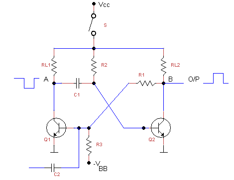
Figure shows the circuit of a monostable multivibrator using NPN transistor. It consists of two similar transistor Q1 and Q2 with equal collector loads i.e. RL1 = RL2 the values of -VBB and R3 are such as to reverse bias Q1 and keep it at cut off. The collector supply Vcc and R2 forward bias Q2 and keep it at saturation. A trigger pulse is given through C2 to obtain the square wave.

Initial Conditions:
Let us suppose that in the absense of a trigger pulse and with S closed, initially the circuit is in its stable state i.e. Q1 is OFF (at cut-off) and Q2 is ON (at saturation).
When Trigger Pulse is applied
Let us see as what happens when the trigger is applied.
- If positive trigger pulse is off sufficient amplitude, it will override the reverse bias of the E/B junction of Q1 and give it a forward bias, Hence Q1 will start conducting.
- As Q1 conducts, its collector voltage falls due to voltage drop across RL1. It means that potential of point A falls (negative going signal). This negative going voltage is fed to Q2 VIA C1 where it decreases its forward bias.
- As collector current of Q2 start decreasing, potential of point B increases (positive going signal) due to lesser drop over RL2. Soon, Q2 comes out of conduction.
- The positive going signal at B is fed VIA R1 to the base of Q1 where it increases its forward bias further. As Q1 conductors more potential of point A approaches 0V.
- This action is cumulative and ends with Q1 conducting at saturation and Q2 cut-off.
Return to initial Stable State:
- As point A is at almost OV, C2 starts to discharge through saturated Q1 to ground.
- As C1 discharges, the negative potential at the base of Q2 is decrease. As C1 discharges further Q2 is pulled out of cut-off.
- As Q2 conducts further, a negative going signal from point B VIA R1 drives Q1 into cut-off.
Hence, the circuit reverts to its original state with Q2 conducting at saturation and Q1 cur-off. It remains in this state till another trigger pulse comes along when the entire cycle repeats itself.
The width of duration of the pulse obtained at the collector or output of either transistor (Q1 or Q2) of the monostable multivibrator is given by the expression
T = 0.69 R2 C1
Emitter Coupled Monostable Multivibrator
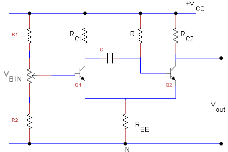
Below figure shows the circuit diagram of an emitter coupled mono-stable multi-vibrator.

It can be observed that the feedback resistive coupling network from the collector of transistor Q2 to the base of transistor Q1 is absent. instead, the regenerative feedback at the change over from one state to other is provided by the common emitter resistor REE. The absence of any coupling from the collector of the transistor Q2 makes it an excellent output point. This has the further advantage of making the mono stable period independent of any load variation. Further the common emitter resistor voltage drop VE, Swamps the temperature variation in VBE, on with temperature and thus makes time period or delay period stable. Further it is possible to have the voltage controlled delay, by controlling delay , by controlling the collector current to the transistor Q1 during quasi-stable state. The collector current of transistor Q1 can be varied by changing the forward bias of the transistor Q1.
The emitter coupled mono-stable multi-vibrator has the limitation of lower input voltage. In the normal stable state transistor Q2 is in the saturation region and transistor Q1 is OFF. On application of an appropriate trigger pulse, the transistor Q2 starts to work in the active region reducing the common emitter voltage and forward biasing the transistor Q1. When transistor Q1 begins to conduct its collector voltage falls from VCC. This is a negative change and is transferred by the timing capacitor C, the base of the transistor Q2 reducing the forward bias. Thus both the transistors are in active region and regenerative feedback ultimately forces transistor Q2 OFF and transistor Q1 in the ON state, which may be in the active region of saturation region depending upon the circuit.
Mono stable Multi vibrator Using OPAMP
The circuit shown in figure shows a deferential input operational amplifier acting as monostable multivibrator. In the permanently state of this circuit the amplifier output is at positive saturation, terminal B is clamped to earth by diode D1 and terminal A is positive with respect to earth by an amount of βV10 (sat),
where
β = (R2 /(R1 + R2))
It is assumed that the resistor Rs is much greater than R1 so that its loading effect may be neglected. If the potential at the point A is brought down to earth by the application of a sufficiently large negative pulse the circuit switches regeneratively to its temporarily stable state in which the amplifier output is negative saturation. Terminal A is then negative with respect to earth by an amount -βV02 (sat) and the potential negative at B falls exponentially as C charges down through R, diode D1 is reverse biased. The circuit switches back to its permanently stale state when the potential at B reaches the value -βV02 (sat).
555 Timer Circuit as Monostable Multivibrator
Figure shows the circuit diagram of monostable multivibrator using a 555 timer IC. If the output is low, application of a negative going pulse to the traigger input sets the flip flop (Q goes low), drives the output high, and turns off Q1. Capacitor C is then charged through RA until the voltage of the threshold input. If the trigger input has returned to high level, the output of the threshold comparator will reset the flip flop (Q goes high), drive the output low, and discharge C through Q1.
Monostable operation is initiated when the trigger input voltage falls below the trigger threshold. Once initiated, the sequence will complete only if the trigger input is high at the end of the timing interval. Because of the threshold level and on-state voltage of Q1, the output pulse duration is approximately
tw = 1.1 RA C
The threshold levels and charge rates are both directly proportional to the supply voltage. VDD. The timing interval is, therefore independanet of the supply voltage, so long as the supply voltage is constant during the time interval.
Applying a negative going pulse simultaneously to the reset and trigger terminals during the timing interval will discharge C and re-initiate the cycle, commencing on the positive edge of the reset pulse. The output is held low as long as the reset pulse is low. When the reset pulse is not used, it should be connection to VDD to prevent false triggiring.
Uses of Monostable Multivibrator
- The falling part of the output pulse from MMV is often used to trigger another pulse generator circuit thus producing a pulse delayed by a time T with respect to the input pulse.
- MMV is used for regenerating old and worn out pulses. Various pulses used in computers and telecommunication systems become somewhat distorted during use. An MMV can be used to generate new, clean and sharp pulses from these distorted and used ones.
Monostabel Triggering
To change the monostble multivibrator state from the stable to quasi-state the external trigger pulses are to be applied. In general the negative triggering has grater sensitivity, because here the negative pulse amplitude should be enough, so as to bring the operating point from saturation to active region. Secondly when the base emitter voltage of a junction changes from forward bias to reverse bias, its input impedance is continuously rising, which avoids the loading of the triggering source. It should be further noted that the monostable period is affected by this method.
The positive pulse triggering has sensitivity, because to turn of the transistor from the OFF state, it is necessary to feed the excess stored charge in the base such that the amplitude of triggering pulse is enough and is derived from a low impedance source, which can supply a peak demand current to turn on.
