RLC Filter Circuit
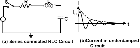
Consider the series RLC filter circuit shows in Fig. 1(a). If a unit step function is applied, we see that:
- Initially there is not current at the instant the switch is closed current must rise in a finite time, because the inductor opposes any instantaneous change in current.
- When the capacitor is fully charged then the flow of
current stopped.

By applying Kerchief's voltage law we have
Vi = VR +VL + Vo
![]()
Above equation (1) is a complex differential equation. However, the solution is of this equation is.

where
I is the instantaneous current
Vi is the magnitude of the step input voltage
R is the resistance
C is the capacitance and
L is the inductance
Equation (1) is the equation for the circuit current I as shown in Fig. 1 (b). It can be partially written as:
I = Io e-x sin wt
Analysis of equation ( 2) shows that
- The maximum value of the current Io is given by the relation.

- The current decays exponentially with time constant L/R. The exponential decay of the maximum value shown in dotted line is considered to be practical complete when
Rt/2L = 5 Or t = 10(L/R)
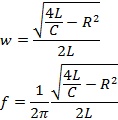
- The current is sinusoidal in nature arid the frequency is given by:

Hence,
it is concluded that the current rises to a maximum value Io and then decays exponentially to zero while oscillating sinusoidally as shown in Fig, 2(b)
Damping Characteristic
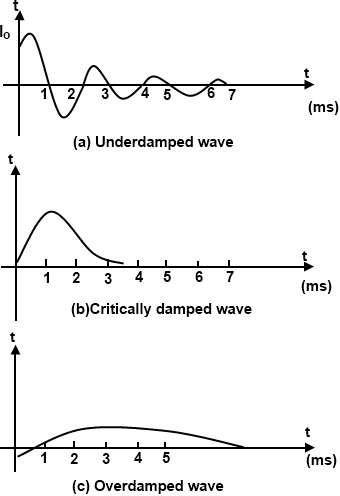
The loss of energy in any wave or curve is called damping, which causes decreases, in amplitude. Basically damping can identify by three types called critical damping, underdamping and overdamping.
In equation (2), the value under the square root sign,[(4L/C) — R2] is so important. Values for maximum current and the frequency of oscillations are controlled by it. Depending on whether (4L/C) is greater than, equal to or less than R2, this quantity may be any one of three forms, a positive real number, a zero or an imaginary number.
Let us consider these three forms one by one:
(I) When (4L/C) — R2 > 0
In such case the current in the circuit reaches its maximum value l, oscillates sinusoidal, and ultimately decays exponentially to zero. Exponentially decaying sinusoidal oscillation classify this circuit as under damped. A under damped circuit is also called as a ringing circuit. Hence, a circuit is said to be under damped when a step input applied to it results in exponentially decaying sinusoidal oscillation.
(II) When (4L/C) —R2 = 0
In such case, the maximum current value has no meaning. The frequency of oscillation is zero because R2 = (L/C). The LC circuit under such conditions is called to be erotically damped. It does not oscillate but decay from maximum to zero. Hence a circuit that goes to its final steady state position in the shortest possible time without oscillating whenever a step input is applied. A waveform that does not change with time is called the steady state:
(III) When (4L/C) — R2 < 0
In such case, there is a negative number, its square root is an imaginary number because R2 > (4L/C). It means that maximum current Io has an imaginary value and the frequency oscillation is also imaginary. In simple word, the current never reaches its maximum value and under such cases does not
oscillate. The circuit is called as over damped. Hence a circuit is in exponentially said to be under damped when a step input is applied to it results in exponentially decaying sinusoidal oscillations.

Ringing Circuit
A circuit in which exponentially decaying sinusoidal oscillations are obtained classify as under damped, under damped circuit is also known as ringing circuit. Damping constant say K. (i.e. 1/(2R ![]() ) is small, the circuit will ring from many cycle.
) is small, the circuit will ring from many cycle.
If the damping is small enough the response approaches an under damped since wave. We can easily calculate the amplitude of oscillation if we know that the initial magnetic energy stored in the inductor is converted in to electric energy in the capacitor at the end of one quarter cycle. Thus
½ LI2 = ½ CV2
Or
![]()
A ringing circuit can be used to generate a sequence of pulses regularly spaced in time. For this purpose a transistor is used before the circuit. The sequence starts when the device delivering current I is cut-off. These pulses find application in many timing operation.
