FM Balanced Slope Detector
A balanced slope detector is an improved version of the slope detector. The drawback of harmonic distortion is removed in this detector by using two slope detectors instead of one as in a single-tuned slope detector.

Circuit Description
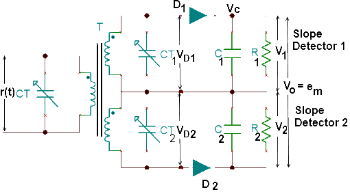
The circuit diagram, shown in Figure (a), has two slope detectors marked slope detector 1 and slope detector 2. Both the slope detractors are called balanced because they have identical components as follows:
Slope detector 1: It consists of a detector diode D1, filter capacitor C1, load resistor R1, and variable capacitor CT1. The variable capacitor CT1 is called the tuning capacitor because it is adjusted to tune the upper winding of the secondary Winding of the input transformer T.
- Slope detector 2: It consists of a detector diode D2, that is identical to D1. It also has filter capacitor C2, load resistor R2, and variable capacitor CT2. The tuning capacitor CT2 tunes the lower winding of the secondary winding of the input transformer T.
The two slope detectors are balanced because C1 = C2, R1 = R2, and D1 is identical to D2. The upper and lower windings of the secondary windings of the center-tap transformer T are also identical.
The primary winding of the input transformer T is tuned to the central frequency of the carrier signal fc by using the tuning. capacitor CT. The secondary windings are tuned to different frequencies so that the circuit is staggered tuned. The outputs of the detector diodes D1 and D2, are filtered by C1, R1 and C2, R2, respectively. The voltage V1. which is developed across R1, and voltage V2, which is developed across R2 are added together between the points E and F to get the final output voltage Vo, which is the modulating voltage em.
Circuit Operation
The operation of the circuit can be explained by considering the two slope detectors separately.
Slope Detectorn 1
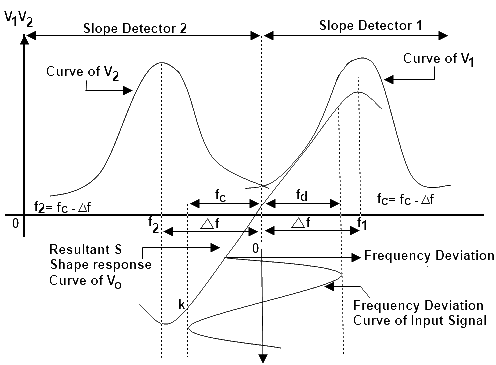
The resonating frequency of slope detector 1 is set to f1, by adjusting CT1 so that it is greater than fc by an amount of ∆f. As a result, slope detector 1 is tuned to fc, given as:
f1 = fc + ∆f
The signal coupled to the upper winding of the secondary winding of the transformer T has a central frequency fc. If the maximum frequency deviation of the incoming FM signal, r(t), is ±fd, the operating range of slope detector 1 is between fc and (fc + fd), shown in figure (b). Which illustrates the frequency response curve of both slope detectors.
When the incomning signal frequency deviation between fc and (fc + fd), diode D1 is forward biased becouse voltage VD1 increases according to the frequency response response curve of slope detector 1. The diode rectifies this amplitude and frequency modulated signal. Capacitors C1 and resistor R1 then filter the rectified voltage. The voltage so developed across R1 is the positive half of the modulating signal. This can explained by the frequency-deviation curve applied at fcon the frequency-axis of Figure (b). The positive half of the frequency-deviation curve lies in the response curve of slope detector 1. Therefore, the frequency deviations that are greater than are converted into coresponding amplitude by slope detector 1.
Slope Detector 2
Slope detector 2 is tuned to f2, by adjusting the tuning capacitor C2 such that:
f2 = fc - ∆f
The input FM signal whose frequency deviation lies between fc and (fc — df) is converted into corresponding amplitude variations by slope detector 2 because this part of the frequency-deviation curve lies toward the frequency-response curve of slope detector 2. The voltage VD2, developed across the lower winding of the secondary winding of the transformer T is amplitude-and frequency-modulated, which corresponds to the frequency deviation from fc to (fc — df). This voltage, VD2 is rectified by diode D2, because it is forward-biased and the capacitor C2, filters this rectified voltage. The filtered voltage is developed across R2 and, as a result, the output of the balanced slope detector is the negative half of the modulating signal corresponding to the frequency deviations lower than fc.
Combined Response of Slope Detectors 1 and 2
The output of the balanced slope detector is the combined output of the individual slope detectors. Slope detector 1 provides the positive half of the modulating signal across the Output terminals E and F. When D1 is forward-biased, the diode D, is also slightly forward-biased because the voltage developed across the lower winding is very small. This is because slope detector 2 is tuned to (fc — ∆f), while the incoming signal lies between fc and (fc + ∆f)
The conduction of diode D2, results in a small current that flows though R2 from F to D. The direction of the current due to D1 is from E to D through R1
Therefore, when a positive voltage is developed across R1 a very small negative voltage also develops across R2. The sum of these two voltages appears between output terminals E and F.
Thus, the final output is sligtly reduced by a negative voltage developed across R2, because: -
Vo = V1 - V2
A similar action takes place when the incoming FM signal contains the frequency deviations between fc and (fc - df). The diode D2 is forward-biased because appreciable positive voltage VD2 appears across D2. This is because slope detector 2 is tuned towards (fc - df). This frequency-deviation range lies in the negative half of the modulating signal. As a result, the voltage developed across R2 after filtering the rectified output of D2 is the negative half of the modulating signal.
During the conduction of D2, a small voltage also appears across the upper winding of the secondary winding of transformer T. This voltage is small because the upper winding is tuned to (fc — ∆f), while the incoming voltage lies in the frequency range fc to (fc — ∆f). Due to this voltage, diode D2, also supplies a positive voltage across R1. This positive voltage slightly reduces the negative voltage appearing across R2, when summed up between the output terminals E and F. The net voltage is still a negative half cycle of the modulating signal.
The positive and negative halves of he modulating signal are available across the output terminals of the balanced slope detector marked as shown in Figure (b). The overall response of both slope detectors is shown in Figure (b), and the operating range at the curve is marked between the points K and L. This operating range of the overall response curve is a straight line, and therefore, the operation is linear. This removes the; nonlinear behavior of a single-tuned slope detector, and the higher harmonics are not generated in a balanced slope detector.
The overall response curve takes the shape of the letter S, as shown in the Figure (b). This is called S-response of the FM detectors.

Drawbacks of Balanced Slope Detector
Although a balanced slope detector is better than a slope detector. it has following drawbacks:
- The detector has three windings in the input transformer T, and all of them are tuned to different frequencies. The primary winding is tuned to tha central frequency of the carrier, fc, using the tuning capacitor CT. The two secondary windings are tuned to (fc + ∆f) and (fc — ∆f) using the tuning capacitors CT1 and CT2. The alignment of three tuned circuits, called staggered-tuned, is a difficult task that should be accomplished with accuracy to obtain a linear S-curve.
- This slope detector also responds to the amplitude variations of the input Therefore, it may not provide a true modulating signal.
- The operating frequency range is increased after obtaining an S-shape, but its performance does not improve.
