FM Slope Detector
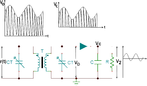
According to the principle of the slope detector, the received FM signal is applied to an LC circuit whose output is an amplitude and frequency-modulated signal. This signal is then passed to an AM detector, which uses a detector diode, D, as shown in Figure (a) to recover the modulating signal, Vo.
The circuit diagram of a slope detector is shown in Figure (a). This circuit is also known as a single-tuned slope detector.

The transformer, T, shown in Figure (a), passes the received signal to the diode D. The secondary winding of the transformer T is used as the inductor and a capacitor. CT is connected in parallel to constitute an LC resonating circuit. The secondary winding is tuned to a frequency slightly less than the resonating frequency of the LC resonating circuit the resonating frequency of the resonating circuit. fo is greater than the central frequency of the input signal fc.
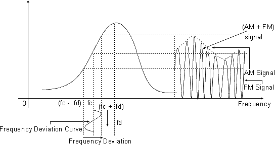
Symbolically. fo > fc as shown in below Figure (b).

If the maximum frequency deviation in the input FM signal is ±df. the operating frequency range of the voltage versus frequency curve of Figure (b) will be (fc -fd) to (fc + fd), as clearly shown in Figure (b). This range covers the linear region of the curve. The frequency variation is converted into the corresponding voltage variation, and the voltage available at the anode of the diode D carries both the amplitude variation and the frequency variation in direct proportion to the modulating signal. This is marked as Vo in Figure (a).
The detector diode D rectifies the secondary voltage VD, which is marked as r(t) in Figure (a). The rectified voltage is used to charge the capacitor C up to the peak values.
The capacitor discharges through the resistance R to develop the modulating, voltage Vo. This modulating voltage is the voltage em, as marked in Figure (a). As a result, the slope-detector circuit demodulates the received signal and recovers the original modulating signal.
Applications
A Frequency Modulation (FM) slope detector is a type of circuit used to demodulate FM signals. It takes advantage of the fact that the amplitude of the signal changes as the frequency of the input signal deviates from the center frequency. This type of detector is not as commonly used as other FM demodulation techniques like the Foster-Seeley discriminator or the phase-locked loop (PLL), but it still has some applications:
- Radio Receivers: FM slope detectors were historically used in early FM radio receivers. They can be simple and cost-effective solutions for demodulating FM signals, making them suitable for consumer-grade radios.
- Educational Purposes: FM slope detectors are relatively simple in design compared to more advanced demodulation techniques. They can be used as educational tools to help students understand the basic principles of FM modulation and demodulation.
- Low-Cost Applications: In situations where cost is a major consideration, such as very basic communication systems or hobby projects, FM slope detectors might be chosen due to their simplicity and lower component count.
- Signal Monitoring: FM slope detectors can be used for monitoring purposes where the demodulated signal quality is not of utmost importance. For instance, in scenarios where the primary goal is to detect the presence of an FM signal rather than obtaining high-fidelity audio or data.
- Obsolete Technology Preservation: While FM slope detectors are not commonly used in modern communication systems, they might find a niche in preserving or emulating older communication technology or as part of vintage radio restoration projects.
- Experimental Circuits: Electronics enthusiasts and hobbyists might experiment with FM slope detectors as part of their projects to learn about analog circuit design and signal processing.
- Signal Detection in Simple Transceivers: In very basic two-way communication systems, where the emphasis is on simplicity and cost reduction, FM slope detectors might still find use for detecting incoming FM signals.
It's important to note that due to the limitations of FM slope detectors, they are not suitable for applications that require high demodulation accuracy, low distortion, or good performance under varying signal conditions. More advanced FM demodulation techniques like phase-locked loops (PLLs) and digital signal processing methods have largely replaced FM slope detectors in modern communication systems due to their better performance and versatility.
Drawbacks of FM Slope Detector
The FM slope detector, a specific type of frequency demodulator, has its own set of drawbacks that limit its applicability in various contexts. Here are some of the drawbacks of an FM slope detector:
- Limited Frequency Range: FM slope detectors are most effective within a narrow range of frequency deviations. Outside this range, their performance can degrade significantly, leading to inaccuracies in demodulation.
- Sensitivity to Signal Amplitude: The accuracy of an FM slope detector is influenced by the amplitude of the input signal. Variations in signal amplitude can result in errors in the demodulated output, leading to distorted audio or data.
- Frequency Drift and Centering: Like other FM demodulation methods, FM slope detectors are sensitive to frequency drift and deviations from the center frequency. If the center frequency shifts due to factors like temperature changes or component tolerances, the demodulation accuracy can suffer.
- Susceptibility to Noise: FM slope detectors are prone to noise interference, which can lead to inaccurate demodulation. The demodulated output can be affected by noise components in the received signal, leading to reduced signal quality.
- Nonlinear Behavior: FM slope detectors are inherently nonlinear devices, which means they don't exhibit a linear response over a wide range of input amplitudes and frequency deviations. This nonlinearity can introduce distortion in the demodulated signal.
- Lack of Flexibility: FM slope detectors are generally designed to work with a specific range of input signal parameters. They lack the adaptability and flexibility of more advanced demodulation methods like phase-locked loops (PLLs) that can handle a broader range of input conditions.
- Demodulation Accuracy: The accuracy of FM demodulation using a slope detector might not meet the standards required for high-quality communication or data transmission. In applications where accuracy is crucial, such as broadcasting or data transfer, more precise demodulation techniques are preferred.
- Advanced Communication Systems: Modern communication systems often require advanced modulation schemes and high-fidelity demodulation. FM slope detectors may not be suitable for these systems, which demand accurate demodulation and robust performance.
- Frequency Deviation Variation: FM slope detectors rely on the variation in amplitude caused by frequency deviation. However, the relationship between frequency deviation and amplitude variation can change with different input signal parameters, affecting the demodulation accuracy.
While FM slope detectors have their place in certain simple applications, they are limited by their sensitivity to various factors, susceptibility to interference, and lack of accuracy compared to more advanced FM demodulation techniques.
