Principles of Fiber Optics
Step index fiber & light propagation in it
A fiber made of a core and cladding with two reflective indices near and clad is called step index.
In step index the density of the core remains constant from center of edges and the refractive index changes in a step fashion from center of fiber (core) to outer shell (cladding. The refractive index is high in core and lower in cladding. The light in the fiber propagates by bouncing back and forth from the core cladding interface.
The ray propagation in the fiber must be launched into the fiber at one end. The conditions necessary to inject such rays efficiently depends on the fiber structure and characteristic of light.
A typical step index fiber & light propagation in it can be shown by diagram as

Now in light propagation discussion of different terms.
Total internal Reflection
In the above figure 1, there are two rays shown going into fiber. One is the solid line and other is dotted line. The solid line injected at a lower angle than dotted line.
- For doted ray point A is the interface between air and core. At this point the refraction takes place and ray continues at a smaller angle, closer to the center line. The ray then gets the interface between core and cladding at point B. so again the refraction takes place. Therefore ray slightly bends and continues in the cladding. Finally the ray bend again because it exits the fiber at the cladding air interface point C. However this time the ray leaves the fiber. This ray is not confined and does not propagate through the fiber.
- For solid ray in this case, at point B the total internal reflection occurs. This ray is confined to the fiber core.
let us say that angle of incident at core cladding interface is the critical call it a AC, clear from figure and know that the angle of incident for which the θ 2 (opposite side angle) is equal to 90o, is called angle.
i.e Sin∝C = n2 / n1
∝C = Sin-1 (n2 /n1) ---------------- (1)
Where ∝C = critical angle, n1 = index of core, n2 = index of cladding.
So any incident ray with an angle larger than ∝C will propagate in fiber, because of total internal reflection. The solid line (critical ray) makes an angle θC with center line of fiber. So the rays with propagation angles larger than θC will not propagate. That is why when θ1 > θC so the dotted line ray exits the fiber and is not confined to fiber. The angle θC is called the critical propagation angle, which is not same, as (1).
The formula obtained from geometry of figure is
Sin∝C = CosθC = n2 / n1 ------------(2)
Remember that total internal reflection occurs only when light travels from high index to low index media.
Mode Propagation
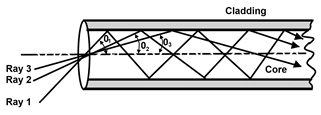
The propagation of light energy in optical fiber takes place at different angles of propagation called modes of propagation. Since all rays with the angles less than θC , propagate in fiber. So on basis of the electromagnetic theory these rays propagate at distinct angles, shown as:

Note that if critical ray is propagating at 11.7o then other rays will propagate at distinct angles below the 11.7o.
Here three rays (ray1, ray2 and ray3) propagating at distinct angles θ1 , θ2 and θ3 respectively. These rays are referred to as modes of propagation.
The total number of modes propagating in fiber depends on the value of θC (critical propagation angle). If θC increases then total number of modes propagating in fiber also increases.
The value of θC depends on n2 / n1 = ncladding / ncore. So the number of modes also depends on this technically the total number of modes increases as the relative refractive index difference ((n2 – n1)/n1) increases.
The modes can be either high order modes or low order modes
.
High order modes
High order modes are those in which the propagation angles are close to the critical angle θC . These high order modes tend to send light energy into cladding. This energy can be ultimately lost particularly at fiber bends. The high order mode will be setup, if the light source to the fiber connection causes a large part of light energy to be coupled to the fiber at relatively large angles, shown as :
High Order Mode Low Order Modes
Low order modes are those in which the propagation angles are much lower than critical angle θC . The low order mode will be setup, if the light source couples the light at shallow angles. In low order mode the energy loss is reduced, shown as:
Fiber Optics Narrow Beam - When light source is misaligned then it tends to setup higher and leaky modes shown as:

Optical Fiber Low Order Mode
this mode is more efficient mode than above two modes to resolve the situations in above modes.
Mode Conversion or Mode Coupling
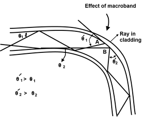
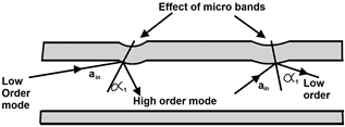
The transfer of light energy from one mode to another mode is called mode conversion or mode coupling. The mode coupling is caused by fiber bends (macro bands and microbands).

Above figure shows two rays (solid and dotted lines) passing through macro band in fiber. When solid line ray of angle θi reaches to point A, than its propagation angle becomes larger than θi. Here we assume that this angle is larger than θC (critical angle). So the ray exits the fiber. Now the θi mode has been converted to a leaky mode (very high order mode) and thus lost.
Similarly the mode propagation at angle θ2 is converted to a higher order mode θ/2 due to band and here θ/2 > θ2. Mode conversion to both the higher order and lower order modes usually takes place.

Here above figure shows the mode conversion caused by a small indentation in fiber known as micro bend. Bothe conversions that in from lower order to high order & from higher order to low order mode is clearly shown by figure.
Thus as a summary we can say that when the light energy propagates in high order modes (mostly low order modes or particular mix of modes than it depends on launch conditions (i.e. then angle of incident of ray entering the fiber end) and so the mode coupling takes place.
Mode distribution
The amount of energy carried by each mode in an optical fiber, usually given in relative terms is called mode distribution.
The mode distribution, because here the power carried by each mode does not change any more.
This means that distribution of light energy among the modes is relatively constant from these on each mode is carrying its fair share light.
Noted that the mode coupling continuous through out the fiber but mode distribution remains relatively unchanged.
It is sometimes desirable to set up the steady state mode distribution over a short fiber length by introducing minute band in fiber.
If fiber is pressed between two blocks, covered with fine sand paper called mode mixing block. The sand paper introduces indentation in fiber and causes increased mode mixing. Since in this method some of the modes become leaky therefore it also causes increased loss.
Meridional & skew wave
The meridional wave or rays are those which pass through the fiber center line. Normally all the rays have been assumed to be meridional.
But in reality a large number of rays travel through fiber without going trough the fiber center line. Thus that ray which propagates in the fiber without crossing the fiber center line is called skew waves or skew rays. The skew waves / rays represent a significant part of the total light transmission. The skew waves are a result of the way the light is injected into fiber and it is nearly impossible and also unnecessary to avoid them. Skew rays are also called spiral rays.
Acceptance Angle & Numerical Aperture
The acceptance angle can be defined as “the range of angles with in which an injected light beam will enter the fiber is called the acceptance angle. To explain the acceptance angle, let us consider a diagram

Here the entering rays shown in fiber are two, one is solid line rays and the other is dotted line ray.
For solid line ray, at point A the refraction takes place and so ray is slightly bends. Thus θa is not equal to θC . Hence the refraction indices involved are of air nair = 1 and of core n1
Similar idea utilizes in dotted line ray propagation also. Thus only those rays are accepted by fiber which enters the fiber edges with in the angle 2θa. This angle 2θa is called the acceptance angle.
The 2θa angle in three dimension is called an acceptance cone, which is limited by the angle 2θa . The cone is formed by rotating the acceptance angle with the fiber line as axis.
To relate the one half of acceptance angle θa with the refractive indices of fiber we can use Snell’s law (at point A of above figure)
Here the term “Sinθa “is called the numerical aperture (NA) and can be defined as: “ The Sine of one half of the acceptance angle is called N-Aperture”. So from (1) we can write mathematical relationship between N.A & θa as:
N.A = Sinθa ------------------(2)
From the eq. (2) it is clear that a large N.A represents a large acceptance angle & vice versa.
.
In terms of refractive indices n1 (core index : ncore ) and n2 (Cladding index : ncladd) we represent N.A as:
Since
N.A = Sinθa = n1 Sinθc ------------ (2A)
Now we know
Since the relation between refractive indices & critical angles is
From Eq. (2) we can easily derive Eq. for half acceptance angle. i.e.
θa = Sinθa => θa = Sin-1 (N.A) By Putting N.A values from (4) we get
Eq. (5) is the relationship of θa & Fiber radius.
The relative refractive index difference is denoted by ∆, which is defined as:
Which is the Eq. for N.A in terms of relative refractive index difference (∆). From Eq. (6) clear that , a large N.A implies a large difference in refractive index (∆). Typically the ∆ is of the order of 0.01 -> 0.03 (means 1 to 3%).
Line Width
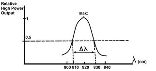
The range of the wave lengths between the two points of half power emission of a light source is called line width.
In other words, the line width of light energy and of a light source is the width in wave lengths between two points where the light energy drops off to one half of its maximum power.

The line width is denoted by ∆. And ∆λ corresponds to the band width ∆f. For narrow line widths, ∆f can be expressed as:
∆f = ∆λ / λo fo -------- Eq. (1a)
∆f = f2 – f1 = band width of light source
f2 – f1 = Half power frequency of light source
λo Center wave length
fo = Center frequency
Clearly the figure shows that power is maximum at 820 nm = λ and drops to half at 810 nm & 830 nm. So its line width will be ∆λ = 830 – 810 = 20 nm
From Eq. (1a) we can say that the bandwidth is the product of relative line width (∆λ / λo ) and the center frequency.
Note that: a line width of the source has serious effect on overall performance of fiber optics transmission system. A large line width a large number of modes for the same N.A & lower the maximum data rate of system.
