Optical Fiber
The transmission media used for the communication of signals from one point to another are copper wires, coaxial cables, wave-guides and radio links. All these media have their own advantages and disadvantages. Recently, the most modern medium of transmission for communication has been developed. This modern medium of transmission, called optical fiber, has presented the new frontier in the field of telecommunication transmission.
Light is an old friend to the human beings. Light was used as a medium for communication in the earliest days. About two hundreds years ago light was used for transmission of information over long distances. But after many years of research and experience gained so far with the new technology, communication has developed into the present state. The idea of harnessing light as a communications medium was transformed into a practical communication system. The practical use of optical fibers was made possible by the perfection of the Laser and manufacturing of hair-thin glass lines called "optical fiber". In the optical fiber a modulated beam of light are used to carry the information on the principle of total internal reflection.
Optical Fiber Construction
Basically optical fibers consist of two parts
- Core and Cladding: these are made from fused silica glass (SiO2) and are optically transparent.
- Coating:
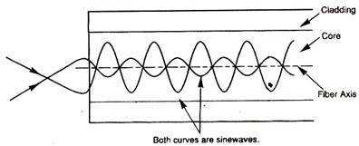
The central portion of the optical fibers is called the core; it is this part in which light rays are guided. That portion which surrounds the core is called cladding. The refractive index of the core is always slightly greater than the refractive index of the cladding. Due to this difference in the refractive indices of the core and cladding, the light rays are always kept within the core of the optical fibers.
During manufacturing of the optical fibers, protective layers of plastic are uniformly applied to the entire length of the fiber. The refractive index of the coating is higher than that of cladding and core, to attenuate any undesirable light in the cladding. This coating can be removed when desired, i.e. (for jointing etc). The coating gives protection to the fibers from external influences and absorbs shear forces. These coatings are usually colored to identify individual fibers in a multi-fibers cable.
Optical Fiber Charactristics
The fiber loss mean's wasting of energy (power) in fiber. If Pin is the input power and Pout is the output power of fiber, than fiber loss is defined methematically as:
Loss = Pout / Pin ---------(1)
In decibels (logrithmic unit) the (1) can be
Lossdb = 10 X log(Pout / Pin) ---------- (2)
The unit uses for less will be "decibels per kilometer" because the loss is increases mostly with fiber length. When we solve (1) or (2) and -ve sign comes in answer than don't worry it shows that Pout is smaller than Pin because of fiber loss.
Remember that word loss implies the -ve sign. Usually all losses are wave length dependent & can be minimized by carefully choosing the operating wave length.
TYPE OF Optical Fiber MODES
A mode is a stable propagation state in optical fibers. When light rays travel along certain paths through the optic fibers, the electromagnetic fields in the light waves support each other to form a stable field distribution. Thus light travels in the fibers. These stable operating points (standing waves) are called modes. If the light follows other paths then a stable wave will not propagate through the fiber and hence there will be no mode.
The optical fibers are typed according to the following modes:
SINGLE MODE
In this, the light propagates in a single or fundamental mode in the core. Such fibers with only one mode are called single-mode fiber. It allows a single light path, and typically used with LASER signaling. The single mode fibers can allow greater bandwidth and cable runs than that of multimode but it is more expansive. The single mode fiber has the best characteristics of highest data rates and least attenuation. The single mode fiber is of very small size. It has the core of approximatly 5 to 10 micro meter in diameters.MULTI-MODE
It is further divided into:- STEP-INDEX
- GRADED-INDE
STEP-INDEX MULTIMODE FIBERS
This fiber works in a very simplified way. The word step-index is used because the refractive index suddenly changes at the interface between core and cladding. The refractive index of the core is slightly greater than that of the cladding, thus confining the light to the core, by the principle of total internal reflection. The step-index multi mode fibers collect light easily but have a limited bandwidth.

GRADED-INDEX FIBERS
These are called graded-index fibers because in these fibers the refractive index changes gradually from the core to the cladding and at the boundary between the core and cladding, the change is abrupt. The refractive index decreases gradually from the center of the core to the edge of the cladding. Graded-index multi mode fibers collect light better than small core single mode fibers and have broader bandwidth than step-index multi mode fibers.
Optical Fiber Transmitter
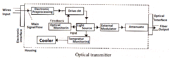
Explanation
Optical transmitter is a device that generates the signal sent through optical fibers. The basic elements of optical fiber transmitter are shown in above Fig:
Electronic Interface
There is wires standard electronic connection or pins energizing the transmitter. They provide power Electronic I/P and Optical O/P signals.
Optical Interface
There are actually the connectors between the light source and fiber may have different forms.
Drive CKT
This depends on application, requirements, data format and the light source.
Electronic Processing
In some transmitters the I/P Electrical signals are electronically processed to put them into of suitable from to drive the light source.
Optical Monitor
It Monitors the O/P of the LASER and provides feedback to the drive CKT so that the O/P power remains stable.
Temperature Monitor
The characteristic of semi-conductor LASER changes in temperature. The life time of LASER decreases with increase in operating temp and the O/P power also decrease which produce some change in 0/p wave length of the light, to keep the operating temp stable the
Thermo-electric coolers are used in optical fiber transmitters these coolers control the temp of LASER.
Attenuation
The optical fiber transmitters should produce some standard level of power and this level should not desired for the receivers, to handle the receiver I/P power, the attenuator is used in the transmitter to reduce the O/P level of the transmitter to a safe value for the receivers.
External modulator
The external modulation means modulation of light source by on external device in order to prevent spreading of wave-length range of light emitted by LASER.
Optical Fiber Receiver
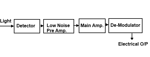
This is a device that converts the optical signal received through the fiber into Electrical from for the use of other devices as an I/P signals; the basic elements of optical receiver either analog or digital are shown below.
Detector
The 1st stage of optical fiber receiver is a detector, which converts the received signal into an Electrical from.
Amplification Stages
In the amplification stages there are 2, stage of amplifier are used which amplifies the converted signal, for further processing.
De modulator or Decision CKT
It reproduces the original Electrical signal from modulated incoming signals.
Light sources
There are 2 following types of light sources which are used in optical fiber T/N system
- Light Emitting Diode
- LASER
Light Emitting Diode (LED)
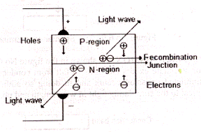
The basic operation of LED is shown in above Fig, the LED is a PN-Junction diode which emitting light, When a small forward biased voltage is applied it its terminals a current flow start across the junction , electrons in N-Region and holes in P-Region flow towards junction where they are combine and release a some energy, the re-combination continues as long as the voltage is applied.In silicon and germanium semi-conductors the released energy is in the from of heat, while in the LED, the released energy appears as light. The semi-conductor material used in the Constructions of LED, for optical fiber system is gallium aluminum arsenide or gallium arsenide, other semi-conductors like gallium arsenide phosphate and gallium arsenide also used.
GaAs LED emits light of 930 mm of wave length while Ga Al As LED, emits light of a wave length of 750mm to 90mm.
LASER (Light Amplification by Stimulated Emission of Radiation)
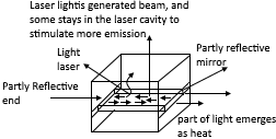
The laser is like a LED but emits light in a different way , resulting in higher O/P power and more directional beam ,the beam is produced by a cavity resonator that reflects light again and again inside the cavity ,the cavity consist no Numbers of mirrors. The light emitted towards one mirror is reflected again and again between the two mirrors thus stimulating emission from electrons. At this way the density of light identical wave-length and phase to become large even at low frequency light, so the stimulated emission began at low I/P current the simplified block diagram of laser is shown in above fig.
Uses of Optical Fiber in Telecommunication System
The fiber optics is superior to metallic conductors as a T/N line for signals because of its high bands –width, low attenuation, interference, low cots and light in weight. Due to these advantages the fiber optic is used in field of telecommunication. Some of the applications of the fiber optic in telecommunication system are given below,
- Because of its very low attenuation, it is used as a junction cables between exchanges, where channel capacity is increased.
- The large band-width of optical fiber makes it suitable for video data T/N reception.
- The fiber optic, also finds used in voice and video communication network (ISDN).
Merits and Demerits of Optical Fiber System
The merits and dements of optical fiber system are following.
Merits
- when high freq signal are propagated through convention coaxial cable ,it loss half of its power only after a few hundred meters where as the optical fiber loss the sauce amount of power in 15km or more .Thus repeater will be required at very long distance.
- The T/N rate is possible on optical fiber is 10GB/sec while in coaxial cable is 1GB/sec.
- Because of very small size and light in weight and large Flexibility, it produces a number of advantages over cupper wires at the installation time.
- As the fiber optic has no electrical conductivity, there fore Grounding and protection are not necessary.
- Using optical fiber the transmission loss is very low.
- Also the long distance transmission is possivle with fibers with out the need to ampligy and retransmits the signal along the way.
- Fiber is lighter and less bulky than equivalent copper cable
- In fiber optic communication, there is no need of electrical connection between the sender and receiver.
- There is no interference in the transmission of light from electrical disturbances such as lighting or electrical noise because the electromagnetic waves generated by electrical appliances cannot interfere with the light signal.
- Optical fiber is more reliable than copper cables.
- Optical fiber can be bending at any signal angle or even in circle.
- The transmission through optical fiber is more secure and private.
- The optical fiber communication provides much higher bandwidth because of uses light, which has much higher frequency than electricity.
- The optical fiber has much lower attenuation, where the attenuation is the communication term referring to distance. Note that length of cable and its resistance can affect the amount of attenuation.
- The fiber optic cable does not leak the signals rather than the copper cable.
- Optical fiber is smaller and lighter than copper wire.
- The optical is free from base rust making them ideal choice under or upper the ground surface.
- The optical fiber communication is relatively soft way to send the data, means that fiber optic cable cannot be tapped and data cannot be stolen from it. Which is possible in any other copper cable.
Demerits
There are also some negative points of fiber optics communication, making their use limited. However to make its use widely the try is in progress. Some negative points of fiber optic communication are:
- The joining of fiber optics cables need greater care because if the Joining is not correct; a lot of attenuation will produce in high Wave length.
- As the fiber optics have no electrical conductivity, there fore additional Copper cable is not used with optical fiber to provide power supply to the repeaters.
- The installation cost is very high as compare to the other types of T/N lines.
- The big and base disadvantage of optical fiber is its cost, means its cost is slightly more expansive than copper cable. However its cast is falling day by day. When it comes down in price, then the fiber will be the choice of everyone for network/communication cabling.
- Since fiber optic cable is relatively new technology so its installation and maintenance needs a expertise, which is not available everywhere.
- We know that the propagation of light is unidirectional. If we need bidirectional communication than two fibers are needed increasing the overall cost of the system.
- The reconnection of two ends of fiber is done by the optic connector, which has very high cost and very time consuming installation.
