SSB Receiver
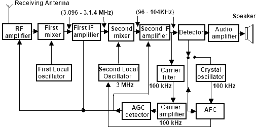
The RF signal is intercepted by the antenna and amplified by the RF amplifier. The amplified RF signal is applied to the first mixer. The second input to the first mixer is from the first local oscillator. The first local oscillator generates a frequency such that the output of the mixer varies between 3.096 and 3.104 MHz for the single sideband received. This signal is then amplified by the first IF amplifier.

This receiver uses the double-conversion method to get the second IF amplifier. The output ofthe first amplifier is provided to the second mixer. The second input to the second mixer is from the second local oscillator, which generates a fixed local frequency of 3 MHz. The output of the second mixer gives the second IF signal, which varies between 96 and 104 kHz. The detector then demodulates the second IF signal. The output the detector is the modulating signal, which is amplified by the audio amplifiers. The amplifiers consist of the audio driver and the audio power amplifier. This amplified audio signal is then given to the speaker.
Reinserted Carrier
To demodulate the SSB the carrier frequency, also called the pilot carrier, is removed. The value of the carrier frequency is 100 kHz. To remove the carrier, a localy generated carrier of 100 kHz is required. You can obtain this two ways. The frequency can either be generated by a local crystal oscillator or obtained from the received signal. A switch is provided in the receiver to connect the detector stage either to the crystal oscillator or to the carrier amplifier, as shown in Figure (a), to reinsert the carrier. This is called the reinserted carrier.
To get the carrier from the received signal, the output of the second IF amplifier is given to a carrier filter. This generates a 100 kHz carrier from this signal. The carrier amplifier now amplifies the carrier, which is removed from the signal. This carrier is then reinserted to the detector, as shown in Figure (a).
AGC
The output of the carrier amplifier is also given to the AGC detector, which generates a dc voltage in proportion to the carrier strength. This voltage, after filtration, is applied to the RF amplifier and the first and second IF amplifiers to control their gains. This produces the audio output at the preset volume level.
Automatic Frequency Control (AFC)
To detect the single side band, the IF frequency must be correctly generated. This depends upon the correctly generated frequency of the local oscillators. To ensure that correct IF frequency is produced, an AFC signal is generated, which corrects the frequency of the second local oscillator.
The output of the carrier amplifier is the carrier frequency of 100 kHz, obtained from the received signal, as shown in Figure (a). This frequency is compared with a locally generated crystal oscillator, which also gives a frequency of 100 kHz. The two input frequencies of AFC are compared, and an error voltage is generated proportional to the difference between the frequencies. This error voltage is applied to the second local oscillator so that its frequency is corrected to get the correct second IF frequency.
Troubleshooting SSB Receivers
The faults that may appear in an SSB receiver are similar to the ones that appear in AM receivers. The procedure for troubleshooting these faults is explained in the topic on AM receivers. In an SSB receiver, the signal injection method is the most helpful. You need to first find out the faulty stage of the receiver by injecting proper signals at the input terminals of each stage. If the audio tone is not heard from the speaker when the signal is injected to a particular stage, it indicates that the fault lies in the stages ahead that particular stale. By progressively checking and injecting the signal at the next stages you can detect the faulty stage. Once the faulty stage is detected, check the various components using the techniques discussed earlier and consult the service manual. Finally, remove the faulty components.
