SSB Transmission
SB transmission, also known as Single Sideband transmission, is a method used in radio communication to efficiently transmit information over a radio frequency. It is a modulation technique that suppresses one of the sidebands and the carrier wave, allowing for more efficient use of bandwidth and power.
In traditional amplitude modulation (AM) transmission, the radio signal consists of a carrier wave and two identical sidebands. However, in SSB transmission, one of the sidebands (either the upper or lower sideband) and the carrier wave are eliminated, resulting in a more compact signal.
By removing one sideband and the carrier, SSB transmission requires less bandwidth and power compared to AM transmission. This efficiency allows for more channels to be accommodated within the available frequency spectrum. It is commonly used in applications such as amateur radio, shortwave broadcasting, and long-distance communication.
To receive SSB transmissions, a compatible receiver is required to demodulate the signal by reinserting the carrier and missing the sideband. This process is known as "single sideband with carrier" (SSB-SC) demodulation.
SSB transmission offers advantages such as increased range, reduced interference, and improved signal quality compared to AM transmission. However, it requires more complex equipment and may be more challenging to tune and demodulate.
There are two methods used for SSB Transmission.
- Filter Method
- Phase Shift Method
Filter Method
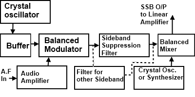
This is the filter method of SSB suppression for transmission. Fig

illustrates the block diagram of this method.
- A crystal-controlled master oscillator produces a stable carrier frequency fc (say 100 KHz)
- This carrier frequency is then fed to the balanced modulator through a buffer amplifier which isolates these two stages.
- The audio signal from the modulating amplifier modulates the carrier in the balanced modulator. The audio frequency range is 300 to 2800 Hz. The carrier is also suppressed in this stage but allows only to pass both sidebands. (USB & LSB).
A band pass filter (BPF) allows only a single band either USB or LSB to pass through it. It depends on our requirements.
Let we want to pass the USB then LSB will be suppressed. In this case.
fc = 100 KHz
Audio range = 300 - 2800 Hz
USB frequency range = fc + 300 to fc + 2800
= 100000 + 300 to 100000 + 2800
= 100300 to 102800 Hz
So this band of frequency will be passed on through the USB filter section
- This sideband is then heterodyned in the balanced mixer stage with a 12 MHz frequency produced by a crystal oscillator or synthesizer depending upon the requirements of our transmission. So in the mixer stage, the frequency of the crystal oscillator or synthesizer is added to the SSB signal. The output frequency is thus raised to the value desired for transmission.
- Then this band is amplified in the driver and power amplifier stages and then fed to the aerial for the transmission.
Advantages
The advantages of single sideband SSB transmission are as follows.
- It allows better management of the frequency spectrum. More transmission can fit into a given frequency range than would be possible with double-sideband DSB signals.
- All of the transmitted power is message power none is dissipated as carrier power.
- The noise content of a signal is an exponential function of the bandwidth: the noise will decrease by 3dB when the bandwidth is reduced by half. Therefore, single-sideband SSB signals have less noise contamination than DSB double-sideband.
Disadvantages
- The cost of a single-side-band SSB receiver is higher than the double-side-band DSB counterpart by a ratio of about 3:1.
- The average radio user wants only to flip a power switch and dial a station. Single-sideband SSB receivers require several precise frequency control settings to minimize distortion and may require continual readjustment during the use of the system.
Phase Shift Method
The phasing method of SSB generation uses a phase shift technique that causes one of the sidebands to be concealed. A block diagram of a phasing-type SSB generator is shown in Fig.

- It uses two balanced modulators instead of one. The balanced modulators effectively eliminate the carrier. The carrier oscillator is applied directly to the upper balanced modulator along with the audio-modulating signal. Then both the carrier and modulating signal are shifted in phase by 90o and applied to the second, lower, balanced modulator. The two balanced modulator outputs are then added together algebraically. The phase-shifting action causes one sideband to be canceled out when the two balanced modulator outputs are combined.
The carrier signal is VcSin2πfct the modulating signal is VmSin2πfmt. A balanced modulator produces the product of these two signals.
(VmSin2πfmt)(VcSin2πfct)
Applying a trigonometric identity.
(VmSin2πfmt)(VcSin2πfct) = 1/2[Cos(2πfc - 2πfm)t - Cos(2πfc + 2πfm)t]
Note that these are the sum and difference frequencies or the upper and lower sidebands.
It is important to remember that a cosine wave is simply a sine wave shifted by 90o A cosine wave has exactly the same shape as a sine wave, but it occurs 90o.
The 90o phase shifters create cosine waves of the carrier and modulating signal which are multiplied in a balanced modulator to produce.
(Vm - Cos2πfmt)(VcCos2πfct)
(Vm - Cos2πfmt)(VcCos2πfct)
Another common trigonometric identity translates this to.
(VmCos2πfmt)(VcCos2πfct) = 1/2[Cos(2πfc - 2πfm)t + Cos(2πfc + 2πfm)t]
Now if you add these two expressions together the sum frequencies cancel while the difference frequencies add producing only the lower sideband.
Cos(2πfc - 2πfm)t
