555 Timer IC as a-stable Multivibrator
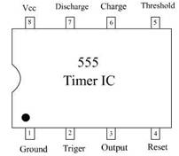
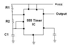
A 555 timer IC is used as an a-stable multi-vibrator as shown in the given Figure (A). The threshold input is now connected to the trigger input (Pin 2), the resister R1, R2, and capacitor C1 for the timing network which sets the oscillator's frequency. The capacitor C2 is connected to the control input.
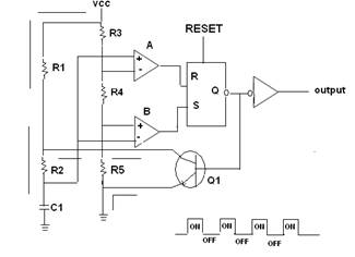
Initially, when the power supply is turned ON, the 555 timer IC capacitor C1 is uncharged and the trigger voltage on pin 12 (B) is zero. In this case, the output of comparator B is high, and the output of comparator A is low, which keeps the base of transistor Q1 low and turns OFF the transistor.
Now C1 starts to charge through R1 and R2 as shown in Figure (b). When the capacitor voltages reach 1/3, the comparator A (Figure B) switches to its low operating state. When the capacitor voltage reaches 2/3, the comparator A (Figure B) switches to its high functional state. This RESET the latch, and this RESET turns ON the transistor Q1 through which the capacitor C1 is discharged.
The following formula gives the frequency of the oscillator.
![]()


| R | S | Q | Q |
|---|---|---|---|
| 0 | 0 | Old State | Old State |
| 0 | 1 | 1 | 0 |
| 1 | 0 | 0 | 1 |
| 1 | 1 | Unknown state | Unknown state |
