Parallel Operation of Transformer
Need for Parallel operation
- When load on the system is increased, it is easy to add more transformers to the system instead of replacing smaller transformer by larger ones.
- If the load on the system is decreased, one or two units can be easily disconnected.
- Efficiency of the power system, with several transformers working in parallel, is more than that one having one big transformer only. Because in case of decrease of load one or more transformers can be disconnected from the system to decrease the iron loss.
Condition for parallel operation
- The transformers should be properly connected with regard to polarity.
- The transformer should have the same voltage ratio.
- The percentage impedance should be equal.
- In case of three phase transformers phase sequence should be same.
Of these conditions (i) is absolutely essential otherwise dead short circuiting will result. Condition (ii) and (iii) should be fulfilled as for as possible. Condition (iv) is also absolutely important.
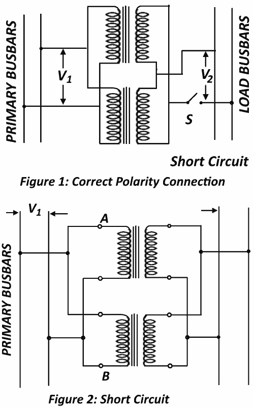
In figure 1, the connection diagram of proper polarities is shown and in figure 2, the wrong polarities connection is shown. This wrong connection produces dead short circuiting.

Equal Voltage Ratio
Consider the case of two transformers working in parallel as shown in figure 1. Assume the no-load voltage of both secondary windings is the same i.e. EA = EB, so no circulating current will result between them on no-load. Neglecting the magnetizing current, the equivalent circuits of transformer can be drawn as shown in figure 3.

Let
ZA, ZB = impedances of transformers
IA, IB = respective currents
V2 = common terminal voltage
I = combined current
Then
For parallel operation
IAZA = IBZB -IZAB --------------------(1)
Where ZAB is resultant impedance of ZA and ZB in parallel.
1/ ZAB = (1 / ZA) + (1 / ZB)
ZAB = (ZA ZB) / (ZZ + ZB)
From equation (1)
IA = IZAB / ZA
And
IB = IZAB / ZB
Or
IA = I ((ZA ZB)/(ZA + ZB)ZA)
IA = I (ZB / (ZA + ZB)) --------------(2)
Similarly
IB = I (ZA / (ZA + ZB)) ---------------(3)
Multiplying both sides of equation (2) and (3) by V2
V2I2 = V2I (ZB / (ZA + ZB))
V2IB = V2I ( ZA / (ZA + ZB))
Let
V2I = Q (combined load KVA)
V2IA = QA (KVA carried by transformer A)
V2IB = QB (KVA carried by transformer B)
So
QA = Q ( ZB / (ZA + ZB)) ----------------(4)
QB = Q (ZA / (ZA + ZB)) ----------------(5)
Example:
Two single phase transformers with equal turns have impedances of (0.5 + j3) ohm and (0.6 + j10) ohm with respect to the secondary. If they operate in parallel, determine how they will share total load of KW at P.f. 0.8 lagging.
Solution:
ZA = 0.5 + j3 = 3.04 | 80.6o
ZB = 0.6 + j10 = 10.02 | 86.6o
ZA + ZB = 1.1 + j13 = 13.05 | 85.2o
Convert KW load to KVA at 0.8 P.f. = 100/0.8 = 125 KVA
Cos φ = 0.8 lagg
Φ = -36.9o
Load = 125 | -36.9o
Now
φA = φ (ZB / (ZAZB))
= (125 | -36.9o x 10.2 | 86.6o ) / 13.05 |85.2o
= 96 | -35.5o
= a load of 96 X Cos 35.5
= 78.2 KW
φB = φ ( ZA / (ZA + φB))
= (125 | -36.9o x 3.04 | 86.6o ) / 13.05 |85.2o
= 29.1 | -41.5o
A load of 29.1 X Cos (45.5o) = 21.8 KW
