Three Phase Transformers
Three phase power distribution and transmission systems require the use of three phase transformers. Three phase transformers can be used as a single unit three-phase transformers or three-phase transformer can be make from three single phase transformers units. Both types have their own importance.
Transmission of electric power at higher voltages is much efficient and economical than that at lower voltages. These higher voltages are possible due to three phase system. That is why three phase transformers are used for the transmission and distribution of electric power. A three-phase transformer can be made i.e. a single unit three phase transformer or by using three single phase transformers connected in a three-phase bank, both types have their own importance in particular cases. A three-phase transformer (of single unit) is lighter, smaller, cheaper and more efficient than three single phase units. However, it is more difficult to transport and replace in the event of breakdown single unit three phase transformer than three single phase units. Figure 1. shows the way of connecting three single phase units to the line.
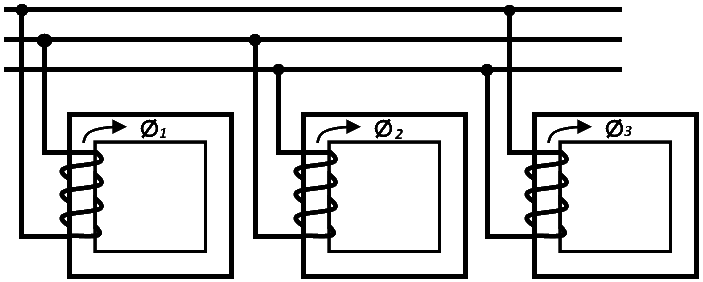
Figure 1: Connection of three single phase transformers to line
Construction and Working
The basic working principle of a 3-phase transformer is same as that of a single-phase transformer. Like single phase transformer, the three-phase transformers are also of core type and shell type as shown in Figure 2. In 3-phasc core type transformer, the core has three limbs. All have windings over them. The cores of a shell type transformer have five limbs. Three of these limbs contain windings and two side limbs are empty. The primary and secondary windings in each type are wrapped one over another to reduce leakage flux, In the figure shown, H.T. means high tension winding and L T means low tension winding.
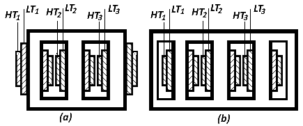
Figure 2: Three Phase Transformer (a) Core Type (b) Shell Type
Winding Connections
The method of marking and identifying the terminals of a three-phase transformer is given by British standard 171 (B.S. 171). The higher voltage winding bears capital letters A, B, C, and the low voltage winding mall letters a, b, c. Sometimes a third winding called tertiary is used which is represented by 3A, 3B, 3C.
In general, the two ends of a winding will be given suffixes and marked A1, A2. But if tapping is brought out or there are sections of the same windings, the marking will be in sequence i.e. Al, A2, A3... See Figure 3.
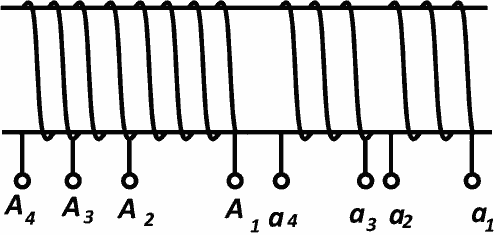
Figure 3: Three Phase Transformer Winding Connection
It is important that the directions of the winding shall be the same for both primary and secondary windings, so as to ensure that voltage VA2A1 is in-phase with Va2a1.
Victor Groups
Thee phase transformers are all allotted symbols giving the type of phase connection and the angle of advance. The angle of advance is taken in passing from the phasor representing the voltage of the high voltage winding to that of the low voltage phasor at the corresponding terminal. The angle is indicated in terms of a clock face as shown in Figure 4. The high voltage phasor being at 12 Oo clock (zero) and the corresponding low voltage phasor at the hour hand number.
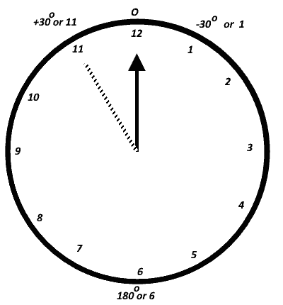
Figure 4: Deference of angle between h.v. & I.v. phasors
The high voltage phasor’s connection is represented by capital letters (Y or D) and the low voltage phasor connection is represented by small letters (y or d). For example, “dy11” represents high voltage delta, low voltage star and angle of advance is at 11 Oo clock i.e. + 30o. Also note that “Z” is for zigzag connection.
Different groups are shown in Fig. 5.
Group - I - Phase displacement = Oo
Examples Dzo, Ydo, Yyo
Group - 2 - Phase displacement = 180o
examples Yy6, Dd6, Dz6
Group – 3 - Phase displacement = 30o
Examples Dy1, Yd1, Yz1
Group – 4 - Phase displacement = Oo
Examples Dy11, Yd11, Yz11
Some of these groups are discussed as follows:
Ddo: This group consists of a h.v. delta, low voltage delta and with zero phase displacement. This type of connection is suitable for large low voltage transformer. Because delta connection requires more turns per phase of smaller section.
Yyo: This group consists of a h.v. delta, low voltage star with zero phase displacement. This type is economical for small h.v. transformers. Because the star connection minimizes the turns per phase and the winding insulation.
Dd6: This group consists of h.v. delta, L. V. delta and with phase displacement of 180°. This connection is suitable for large L.V. transformers.
Dy11: In this type h.v. delta, star and phase displacement is + 30o.
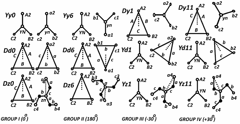
Figure 5: Standard Connections for Three Phase Transformers
