Rotating Core and Constant Current Transformers
Rotating Core Transformer
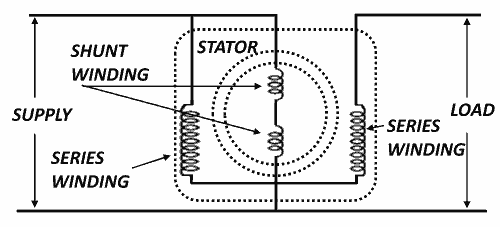
It is also called induction regulator. It works on the principle of induction. It is like an induction motor, whose primary is connected to a constant voltage source and secondary produces variable voltages. This type of transformer consists of a laminated stator core and a rotor core. Series windings are placed in the stator core and shunt windings are wrapped over the rotor core. By changing the position of rotor with respect to the stator, the voltage produced in the series winding can be controlled. The circuit diagram shown in figure.

This type of transformer has the advantage that the voltage can be changed without changing the winding. It has simple and rigid construction. It can withstand overloading.
Applications
It is used where constant voltages are required, like in electronics and control circuits. It can also be used in laboratories as a variable voltage source.
Constant Current Transformer
In general transformers provide constant secondary voltages and a change of load is accompanied by a corresponding change of current. there are conditions where a constant current is desired, the most common being series street lighting.
The construction of the transformer is such that the primary and secondary can move with respect to each other. The primary coil my be fixed, and the secondary may move, or the secondary coil may be fixed, and the primary may move. Both types are found in practice.
In which the primary is stationary and the secondary is movable. The load consists of a number of lamps connected in series. The secondary is suspended from a lower, which is counter weighted. A dashpot is provided to prevent rapid fluctuations in the position fo the moving coil.
Operation
Assume that the secondary coil is floating, that is free to move either up or down, and delivering a certain current to a series load. The currents in the primary and secondary flow in opposite directions, there is repulsion between the two coils. Assume that the load resistance changes, for example decreases. This change of load (i.e. decrease in load resistance) can be produced by short circuiting one or more lamps. Because of the decreased load resistance, first the secondary and then the primary current tends to increase. This increase the repelling force between the two coils. Which causes the secondary to move away from the primary. The leakage flux between the two coils is thus increased and this reduces the secondary induced voltage. Similarly, if load resistance is increased by adding more lamps to the circuit a reverse process like that of the above will appear and the current of the circuit remains constant.
This type of transformer has the draw back of power factor at higher values of leakage reactance.
