Parameters And Equivalent Circuit Of Induction Motor
In an induction motor, the transfer of energy from the stator to the rotor takes place entirely inductively. Hence an induction motor acts like a transformer with a stator forming primary and a rotor forming the secondary. Like in a transformer, here also the primary and secondary circuits are represented by equivalent elements called parameters of the induction motor.
STATOR CIRCUIT
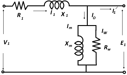
When voltage "V1" is applied to stator terminals, it drops partly in the stator impedance i.e. winding resistance "R1" and reactance "X1" and partly is opposed by stator induced e.m.f. E1.
V1 = E1 + I1R1 + JI1X1
Where "I1" is the stator current and is the vector sum of the no-load current "Io" and rotor equivalent current I21. The no-load current "Io" has further two components "Iw" and "Im". The "Iw” is called a working component and is in phase with "V1". It is a current passing through the core resistance R. And it produces a core loss. The component "Im" is called magnetizing component and it lags behind "V1". It is a current passing through the reactance "Xm" and it produces flux in the core. The stator circuit with circuit parameters is shown in the Figure 1.

Figure 1: Stator Equivalent Circuit of Three-Phase Induction Motor
ROTOR CIRCUIT
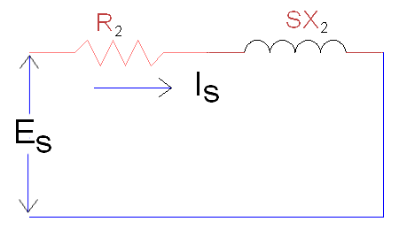
The rotor of the induction motor is like a short-circuited secondary of transformer. The resistance and reactance of the rotor circuit are represented by "R2 and X2 See Figure 2. In running condition i.e. when

Figure 2: Rotor Equivalent Circuit of Three-Phase Induction Motor
The rotor rotates, and the inductive reactance no longer remains equal to "X2". But it equals to slip times the inductive reactance i.e.:
X2 = 2πfL2
During running fr = Sf
Inductive reactance = 2ΔfrL2 = 2πSf L2 = SX2
In figure shown
I = short circuit rotor current.
ES = induced voltage in the rotor circuit.
For simplicity and an easy analysis, the rotor circuit is referred towards the stator by the transformation ratio method. Let the referred values of rotor resistance and reactance be "R21 and X21". The complete equivalent circuit of the induction motor becomes as shown in Figure 3. Thus, the circuit parameters of induction motors are:
Stator resistance R1
stator reactance X1
core resistance Rw.
magnetizing reactance Xm
rotor resistance R2 (or R2)
rotor reactance SX2 (or SX21)

Figure 3: Equivalent Circuit of Three-Phase Induction Motor
