Three Phase Induction Motors
3 Phase induction motors are most widely used in industries. It has the following advantages:
- It is very simple and mechanically strong
- It has sufficiently high efficiency
- It is self-starting
- It requires a minimum of maintenance
However, it has some disadvantages also:
- Its speed decreases with an increase in the load
- Its starting torque is lower than that of an equivalent DC shunt motor
- Its speed cannot be varied without sacrificing some of its efficiency Construction
An induction motor consists of two main parts:
Stator
Rotor.
The Stator:
Stator has three parts
- Frame
- Core
- Winding
Stator Frame:
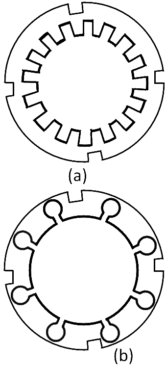
It is made of cast iron. It is used for supporting and protecting the armature core stampings and winding coils end. It has different shapes. A typical shape is shown in Figure. 1:

Figure 1: Stator Frame of Three-Phase Induction Motor Core:
The core of an induction motor is a buildup of silicon steel laminations. The inner part of the core has slots. The slots of large motors are open type but in smaller motors, the slots are semi-closed. See Figure. 2

Figure 1: Core of Three-Phase Induction Motor Windings:
The windings of each phase are made of multi-turn coils and are distributed in several slots per pole. Three phase supply is given to these windings.
Rotor:
The rotor also has a core and windings. It rotates inside the stator. The core of the rotor is made of silicon steel laminations. It has slots on the outer cylindrical surface. Rotors are of two types:
- Squirrel-cage rotor
- Wound rotor or slip ring rotor.
Squirrel-cage rotor:
It is the simplest type of induction motor and is most generally used. It consists of a cylindrical laminated core with parallel slots for carrying rotor conductors. These conductors (also called bars) are permanently short-circuited on themselves at the end. Hence no any extra resistance can be added to it. The slots of the rotor are made of skew type (i.e. these are not quite parallel to the shaft) as shown in Figure. 3. This type of shape reduces the magnetic hum and locking tendency.

Figure 3: Squirrel-Cage Rotor of Three-Phase Induction Motor Wound Rotor:
This type of rotor has windings. These windings are wound over the rotor core for the same number of poles and phases as the stator has. The rotor is made star connected. The other three terminals of the rotor are brought out to connect with the three slip rings. To increase the starting torque, extra resistances can be added to this type of rotor. See Figure 4.

Figure 4: Wound Rotor of Three-Phase Induction Motor
Production Of Rotating Magnetic Field
When stationary coils (wound for two or three phases) are supplied by two or three-phase supply respectively, a uniformly rotating magnetic field of constant magnitude is produced.
Two Phase Supply
Consider a 2-phase, 2-pole stator having identical windings 90 space degrees apart as shown in Figure 5.

The flux waves produced due to the 2-phase supply are shown in Figure 6. Let Ø1 and Ø2 be the instantaneous values of these fluxes. The resultant flux Ør at any instant is the Vector sum of these two fluxes (i.e., Ø1 and Ø2) at that instant.

Now we consider the condition of flux at different intervals. Let Øm is the maximum value of the flux.
- When Ø = 0° then Ø1= 0 and Ø2 = Øm and is negative. Now Ør = Øm and is negative. The value of Ør is represented by a vector pointing
When Ø = 45°, Ø1 = Øm /√2 and is positive, Ø2 = Øm /√2 and is negative.
The resultant flux, Ør is downwards. See Figure 7(i)Again Ør = Øm but shifted through 45° clockwise as shown in Figure 7(ii)
- When Ø = 90°, then Ø1 = Øm and Ø2 = 0 so Ør = Øm and is further shifted through an angle of 45o clockwise. Figure 7(iii)
- When Ø = 135' then Ø1 = Øm/√2 and is positive, Ø2 = Øm/√2 is positive. Again Ør = fm and shifted further 45° clockwise. See Figure 7(iv)
- When 0 = 180° Ø1 = 0° and Ø2 = Øm and Ør = Øm and shifted 45° clockwise. Figure 7(v)

Hence it concluded that:
- the magnitude of the resultant vector is constant and is equal to Øm.
- the resultant vector rotates at synchronous speed.
Three Phase Supply
Consider a 3-phase, two-pole stator having three identical winding and are 120 space degrees apart as shown in Figure 8. The flux waves produced due to the 3-phase supply are shown in Figure 8(c).

Let Ø1, Ø2, and Ø3 be the instantaneous values of the fluxes and Øm is the maximum value of the flux. The resultant flux Ør is the vector sum of Ø1, Ø2, Ø3 Now we consider the condition of flux at different intervals.
When:
θ = 0° then Ø1 = 0, Ø2 = - (√3/2) Øm
Ø3 = (√3/2) Øm
So Ør = 2 X (√3/2) Øm cos 60/2 = 1.5 Øm
the vector Ør is shown downward in Figure 9(i)When:
θ = 60° then Ø1 = (√3/2) Øm, Ø2 = -(√3/2) Øm and Ø3 = 0
So Ør = 2 X (√3/2) Øm cos 30o = 1.5 Øm
The vector Ør rotated through an angle of 60° clockwise. Figure 9(ii).when:
θ = 120° then Ø1 = (√3/2) Øm, Ø2 = 0 and Ø3 = -(√3/2) Øm
Again Ør = 1.5 Øm and is further rotated through an angle of 60° clockwise. Figure 9(iv)when:
0 = 180° then Ø1 = 0, Ø2 = (√3/2) Øm and Ø3 = -(√3/2) Øm
Again Ør = 1.5 Øm and is rotated further through an angle of 60° clockwise Figure 9(iv).

Hence, we conclude that:
- The resultant flux is of constant magnitude i.e. 1.5 times the maximum value of flux.
- The resultant flux rotates around the stator at synchronous speed.
