Three Phase Transformer Connections
The most commonly used connections for three phase transformers are:
- Star/Star
- Delta/Delta
- Star/Delta
- Delta/Star
Star/Star (Y/y) connection:
The connections are shown in Fig. 1(a). This connection is more economical for small size, high voltage transformer. Because the phase voltage is only 1 / √3 of line voltage.
In this connection
Vp = VL/√3
Or
VL = V1 / √3 VP
The primary and secondary voltages are related by turn ratio of the transformer.
Delta/Delta (Δ - Δ) connection
The connections are shown in Fig. 1(b). These types of connections are economical for large size, low voltage transformer in which insulation problem is not so much serious. Because here number of turns per phase is more.
The ratio of primary to secondary line voltages is same as transformation ratio of the transformer.
For delta connection VL = VP
Star/delta (y/ Δ) connection
The connection diagrams are shown in Fie. 1(c). The ratio between the secondary and primary line voltages is 1/√3 times the transformation ratio.
Ratio of the transformer i.e.
This type of connection is generally used to step up the voltage. i.e., in power station to step up the voltages for transmission.
Figure 1: Common 3-Phase Transformer connections.
Different Methods of Phase Transformation of 3-Phase Transformer
We have already studied that by using three phase transformers, different connections can be made for three phase transformations (e.g., star/star, delta/star, etc.). There are some methods by which we can obtain three phase supply with the help of two transformers only. In these methods through the power capacity of transformers decreases but, in some occasions, it becomes more economical.
Some methods of such transformations are:
- Open Δ or V - V connection
- Open Y- Open Δ connection
- Scott-T connection
Open OR V -V Connection
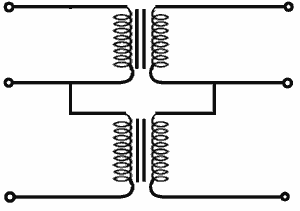
If one of the transformers of a Δ — Δ is removed and 3-phase supply is connected to the primaries as shown in Fig. 2. then three equal 3-phase voltages will be available at the secondary terminals on no-load. This method of transforming 3 phase power by means of only two transformers is called open — Δ or V — V connection.

Figure 2: Open Delta or V - V Connection
Disadvantages:
The average power factor at which the V-bank operates is less than that of the load. Secondary terminal voltages tend to become unbalanced when the load is increased.
Open Y — Open Δ Connection
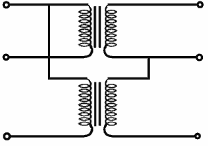
This type of connection is like open Δ connection. The difference is that in this type the primary voltages is given to two phases and there exists also a neutral point. The connection diagram is shown in Fig. 3.

Figure 3: Open Y - Open Delta Connection
This type of connection is used usually to low valued consumers in rural areas. This type of connection has a disadvantage that a return current flows in the neutral of primary circuit.
SCOTT-T Connection
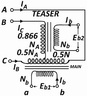
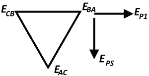
This connection was proposed by Charles F. Scott. This type of connection is used for 3-phase to 2-phase transformation or vice versa. This connection requires two single phase transformers. One transformer (known as main transformer) has Na turns in the primary with midpoint tap the primary. Both transformers have equal turns (Nb) in the secondary. The primaries are connected as shown in the Figure 4. When 3-phase voltages are applied across A, B and C, it will result in:

Figure 4: Scott Transformer
Induced counter voltage in AC and BD in quadrature with each other.
Counter voltage in BD = 0.866 times that in CA.
That is, the voltage across the secondary windings would be in quadrature with each other with their magnitudes equal to each other (since they have the same number of turns).
In other words, two-phase balanced output will be obtained from this connection.

Example 1:
A 3-phase, 50Hz transformer has a delta-connected primary and star connected secondary, the line voltages being 22000V and 400V respectively. The secondary has star connected balanced load at 0.8 power factor lagging. The line current on the primary side is 5A. Determine the current in each coil of the primary and each secondary line. What is the output of the transformer in kW?
Solution:
Δ/Y connection:
But in star connection phase current = Line Current
So secondary line current = 275 A
Output = √3 VL IL Cosφ = √3 X 400 X 275 X 0.8 = 15.24 kW
