An Introduction to Automatic Telephone Systems
An automatic telephone system, also known as a dial telephone system, enables making calls and connections between callers automatically without human operators. The key component that enabled this automation was the telephone exchange. This article provides an overview of how automatic telephone systems work.
Early Manual Phone Systems
Initial telephone systems in the late 19th century required manual switching by human operators to connect calls. An operator physically connected circuits to route speech on request between callers. This manual system was slow, expensive, and prone to errors.
Automatic Switching Exchange
The telephone exchange automated call routing by allowing subscribers to dial numbers directly. It consists of:
- Switching equipment - Electromechanical or electronic switches establish connections between lines to route calls.
- Control equipment - Control circuitry handles call processing, supervision, and billing.
- Software - Stored program control exchanges use computer software and databases to handle advanced functions.
When a caller dials a number, the exchange interprets the digits and automatically connects to the desired destination line by switching between incoming and outgoing circuits. This enabled self-service telephony without human operators.
Key Benefits
Automatic telephone systems provide:
- Faster connections using dial tones and switching equipment
- Lower costs by eliminating human operators
- Higher capacity through increased line concentration
- Additional features like conferencing, call forwarding, etc.
Automatic switching technology revolutionized telecommunications by allowing scalable telephone networks spanning cities, countries, and even globally. It is the foundation for all modern telephone systems we use today.
In the telephone system, two-way communication is carried either by a two-wire or a four-wire system. The two-wire systems are less costly. A general description of the automatic telephone system is given below and is illustrated with the help of a block diagram.

A two-wire line from the telephone set of the subscriber terminates in the Distribution Point (D.P.), which consists of ten pairs for connecting ten subscribers. These ten pairs are extended in the form of underground cables to the cabinet. The underground cable runs from the cabinet to the exchange where it terminates in the Main Distribution Frame (M.D.F-.). The M.D.F. connects the external and internal parts of the system. From the M.D.F. every pair of the individual subscriber is extended to the Subscriber Line Circuit (S.L.C.) inside the switch room. The S.L.C. with the help of a control set seizes the free line finder when the subscriber lifts his handset. The Line Finder (L.F) seizes the free outlet in the 1st Group Selector (G.S) and the subscriber gels dial tone, which means that the system is now ready for dialing. When the subscriber dials the 1st digit 1st G.S. is followed by the 2nd G.S. the 2nd G.S. is followed by the 3rd G.S. and so on up to Final Selector (F.S). The number of G.S. depends upon the number of digits. From the F.S. the line is extended to the S.L.C. of the called subscribers. The loop is completed and the calling subscriber receives a ring from the F.S. while the called subscriber is ring up. In the Below figure, a block diagram of the Automatic Telephone Exchange is shown.
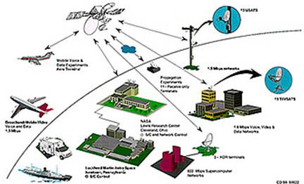
The sketch shown in the figure is a very limited system. In modern systems, many paths are available to allow the connection of any given telephone to another selected from the hundreds of millions of telephones available throughout the world. The transmission links in modern telephone systems may take several different forms, such as overhead wire, buried cable, microwave links, satellite links, and so on. All these systems of transmission are shown in the figure.

Several different forms of transmission links in modern telephone systems
