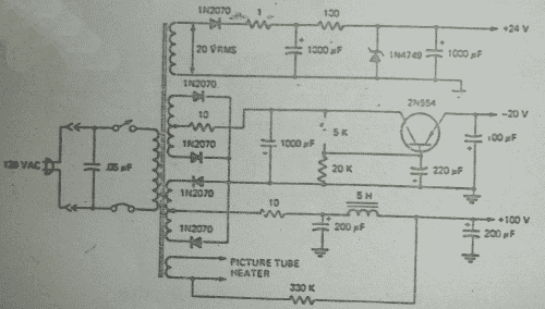
Multi-voltage Supply Circuit
Many electronic systems require multiple different voltage levels for operation. Multi-voltage power supplies generate the required voltages from a single input source. They allow powering of different circuits and components from one supply.
Linear Regulator Design
A simple approach uses multiple linear regulator ICs, each configured to output a specific voltage. For example, a 5V, 3.3V, and 12V regulator can be fed from a 24V source. Each regulator wastes excess voltage as heat to maintain the desired output.
Switching Regulator Design
More efficient designs employ individual buck, boost, or buck-boost converters to efficiently step the input voltage up or down as needed. Switching regulators minimize wasted power compared to linear regulators.
Integrated Multi-Output ICs
Some power supply chips integrate multiple switch-mode converters to generate several outputs. These provide an efficient single-package solution. However, they offer less flexibility compared to discrete regulator designs.
Other Considerations
A careful PCB layout is critical for low noise and stability. Decoupling, filtering, and protection circuits are required for each output. Voltage sequencing and supervision may be needed during startup or shutdown.
Construction of Multi-voltage transformer
The multi-voltage supply circuit shown relies on a multi-winding transformer to generate several AC voltages from a single AC input. The transformer has one primary winding and multiple secondary windings.
When alternating current flows through the primary winding, it produces an alternating magnetic flux in the transformer's core. This changing flux induces AC voltages in each of the secondary windings through electromagnetic induction.
The magnitude of the voltages induced in each secondary winding depends on the number of turns in that winding. More turns in the winding result in more flux linkages, which induces a higher voltage based on Faraday's law of induction. Fewer turns result in lower induced voltages. So the output voltages are directly proportional to the number of turns in each secondary winding.
The current handling capacity of each secondary winding depends on the wire thickness - thicker wires can safely carry more current. So the number of turns determines the output voltage, while the wire gauge determines the available output current.
Rectifiers and filters convert the AC secondary voltages to DC outputs at the desired levels. These DC outputs then power various circuits needing different supply voltages in the electronic system. The multi-winding transformer and diodes provide a simple, reliable way to generate multiple DC voltages from a single AC input.
As shown in the figure, in the upper winding, 20 Vrms a.c. voltages are induced which are then rectified by a single diode 1N2070. Then a low-pass T-type filter is used for filtration of the rectified output. These rectified and filtered voltages are then regulated by a zener IN4749, hence +24V dc is obtained.

In the second winding negative voltages will be induced in the tapped connection. This is then regulated by the transistor in the third winding the positive voltages will be induced in the tapped connection which is then filtered by a low pass filter and +100 voltages are obtained. In the last winding fewer voltages are produced.
Considerations for a multi-voltage power supply:
Transformer Design
- Core material and size - Determines maximum power handling and flux density to avoid saturation
- Primary turns - Chosen to match source voltage and load power needs
- Secondary turns - Each winding is adjusted to produce the desired output voltages
- Wire gauge - Heavier for higher current windings, with insulation rated for voltages
- Winding resistances and reactances - Keep low to minimize regulation effects and losses
- Isolation voltages - Ensure windings can withstand the isolation needs of the supply
Rectifiers
- Fast recovery diodes - Reduce switching losses and voltage spikes
- Current ratings - Must handle maximum expected load currents
- Reverse voltage rating - At least 2x higher than peak secondary voltages
- Heat sinking - Ensure rectifiers can dissipate heat adequately
Filtering
- Capacitors - Smooth the DC outputs by absorbing ripple energy
- Inductors - Can provide additional ripple attenuation
- Load regulation - Additional stages may be needed for very stable outputs
- Ripple requirements - Determine minimum filtering needs
The goal is to design the transformer and rectifier/filter components to meet the load requirements, efficiency, and voltage regulation needs of the power supply. Careful modeling and testing is required to optimize the circuit performance.
