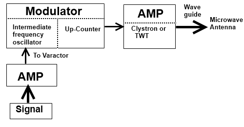
FM Transmitter For Microwave Frequency

Microwave Transmitter
The main components of a microwave transmitter are a microwave power source, a modulator, and , if necessary, a power amplifier. Among the vacuum-tube power sources, the reflex klystron and the backward-wave oscillator are frequency-modulated, and the magnetron is pulse amplitude modulated, by a signal on an electrode. In solid state, by contrast, the modulator is usually separate from the continuous=wave power source. The modulation can be done directly at microwave frequencies or it can be performed at intermediate frequency and shifted to the microwave frequency in an up-converter, which is very much like a down-converter. A common frequency modulator consists of an intermediate-frequency oscillator tuned by the modulation signal applied to a varactor.
The power amplifier can be a klystron or travelling wave tube when higher powers are required For solid state transmitter, transistor or injection locked oscillator amplifiers are common.
Varactor
This is a solid-state diode whose capacitance changes with applied voltage. Varactors are used as harmonic generators to obtain microwave power efficiently from lower-frequency sources such as quartz crystal controlled oscillators in the 10-100 MHz range. Varactors are also used in up-converters and down-converters performing the same functions as similar circuits using resistive diodes, but more efficiently and at the expense of narrower bandwidth.
Amplifier
A microwave amplifier converts a low-power input signal to a higher-power output signal while preserves the amplitude, frequency, and phase of the input amplifier is overloaded, it becomes saturated: the output amplitude tends to remain constant and only the phase and frequency of the signal is preserved.
In an injection-locked-oscillator amplifier, a high-amplitude oscillator is locked in phase and frequency to a Low amplitude input signal coupled into the oscillator circuit. The output of the oscillator is unaffected by the input signal: therefore only the phase and frequency of this type of amplifier are preserved.
High power output is achieved with klystron and traveling-wave tube amplifier has the larger band-width, and the klystron has the higher power. Moderate power can be achieved with transistor amplifiers at frequencies up to about 20 GHz in the linear or saturated modes. At higher frequencies solid state oscillators such as the IMPATT diode can be operated as injection locked oscillator amplifiers in the saturated mode. These are one port amplifiers, the output power emerging from the input port, and a circulator is used to convert them into two port amplifier.
Very low noise levels are achieved in the maser and the parametric amplifier, both of which require power at a single frequency to pump the active element. In the maser, energy is pumped from one atomic level to another, and in the parametric amplifier a varactor is driven b, the pumping signal to provide the nonlinear capacitance required for amplification.
Wave-guide
The most common method of microwave transmission within a system is through hollow circular or rectangular metal tubes of uniform cross section called wave-guides. The microwave energy is confined within these tubes and guided along them.
Antenna
A transmitting antenna takes microwave power from a wave guide and converts it into a plane wave that propagates through space to distant receiving antenna. In the parabolic antenna, a small wave-guide feed horn (fig b) illuminates a large paraboloidal dish which concentrates the energy in a narrow angular beam. In the horn-reflector antenna, a waveguide is expanded into a horn to illuminate a large paraboloidal surface which reflects the microwave energy in a narrow angular beam.

Parabolic Microwave Antenna
