Introduction to ISB Transmission
Principles of ISB Transmission
Independent sideband (ISB) transmission utilizes amplitude modulation but without transmitting the carrier wave itself. In conventional AM, the carrier is modulated by the baseband signal, producing symmetric upper and lower sidebands centered around the carrier frequency. But in ISB, only the sidebands are transmitted - the carrier is suppressed.
This offers a bandwidth efficiency advantage. The carrier contains no information and is redundant. By eliminating it, the same information can be transmitted in half the spectrum. The tradeoff is added complexity in modulating and demodulating without a carrier reference.
Characteristics of ISB
- Only the upper and lower sidebands are transmitted - no carrier
- Twice the bandwidth efficiency of standard AM by eliminating redundant carrier transmission
- Can be demodulated using a product detector to recover audio from the beating sidebands
- Sensitive to phase instabilities since carrier must be reinserted with precise phase for demodulation
- Requires good linearity and low distortion to avoid interfering with sideband-to-sideband leakage
Generation of ISB Signals
ISB signals can be generated using a balanced modulator. This produces DSBSC (double sideband suppressed carrier) which contains both AM sidebands. A DSBSC signal can also be created by taking a conventional AM signal and filtering out the carrier while passing the sidebands. Careful filtering is required to fully suppress the carrier.
Applications of ISB
- Efficient voice communications - ISB provides good audio quality with only the necessary sidebands.
- Radar and navigation systems - the suppressed carrier prevents interference at the carrier frequency.
- Satellite communications - conserves uplink power by only transmitting sideband energy.
- Frequency diversity schemes - allow redundancy with sidebands on separate frequencies.
- Microwave radio links - ISB can transmit two independent audio channels in one channel's bandwidth.
- Low-power two-way radio - ISB voice links increase battery life.
Merits of ISB
- Twice the bandwidth efficiency of standard AM
- Prevents carrier interference issues in radio systems
- Enables efficient voice communications in minimal bandwidth
- Saves transmitter power in satellite and microwave links
- Allows frequency diversity with sidebands on separate bands
Demerits of ISB
- Susceptible to phase instabilities without the carrier
- Demodulation requires careful carrier re-insertion
- Affected by non-linearities and sideband-to-sideband leakage
- Generally more complex generation and demodulation
- Required perfect carrier suppression adds filtering challenges
In summary, ISB provides an efficient technique to communicate information by amplitude modulation without transmitting an actual carrier wave. With careful implementation, the suppressed carrier approach can save bandwidth and prevent interference while still allowing high-quality voice transmission through the modulation sidebands. The merits make ISB well-suited for radio communications links where efficiency and spectrum conservation are priorities.
Generating ISB Signals
There are two main techniques to generate ISB signals:
- Balanced Modulators - This circuit drives the carrier input of a balanced mixer with the baseband signal. When the carrier input is nulled, a double sideband suppressed carrier (DSB-SC) output is produced containing just the AM sidebands.
- Carrier Suppression - Start with a conventional AM signal. Use precise filtering such as a notch filter to remove the carrier, leaving only the sidebands. Stringent suppression is required.
Either approach requires high linearity and low distortion modulation to avoid leakage between sidebands which can interfere with demodulation.
ISB Demodulation
Since no carrier is transmitted, it must be reinserted to demodulate and recover the baseband signal. This is done using a product detector or synchronous detector. The regenerated carrier must be at the precise original frequency and phase. Any instability or inaccuracy in carrier reconstruction causes distortion.
Phase-locked loops help tune precise carrier tone generation. Filters select each sideband separately prior to demodulation. The outputs are then combined to restore the full baseband information.
Performance Tradeoffs
The ISB efficiency gains require balancing performance tradeoffs:
- Bandwidth efficiency vs. demodulation complexity
- Carrier interference prevention vs. susceptibility to phase noise
- Power savings vs. amplification linearity requirements
- Spectrum conservation vs. strict filtering needs
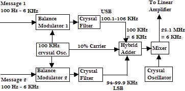
Independent Sideband transmission uses two sidebands that are independent of each other. As shown in the block diagram.

- ISB essentially consists of two SSB channels added to form two sidebands around the reduced carrier. Each sideband is quite independent of the other. It can simultaneously convey totally different transmissions.
- Each 100 Hz - 6 KHz channel is fed to its own balanced modulator, each modulator also receiving the output of the 100 KHz crystal oscillator. Each modulator modulates each message (100Hz to 6KHz) on the frequency of 100 KHz.
- The USB filter and LSB filter suppress the unwanted sideband in such a way that one filter suppresses the lower sideband and the other filter suppresses the upper side band respectively.
SO
USB = 100.1 - 106 KHz
LSB = 94 - 99.9 KHz - Both outputs are added at the hybrid adder with the 10% reduced carrier.
- The output is then fed to the balanced mixer where it is mixed with the output of the crystal oscillator, the frequency is then raised to 28.1 MHz +- 6 KHz.
- The resulting RF ISB signal is then amplified by the linear amplifier, until it reaches the ultimate level then is fed to the antenna for transmission.
