Pre-emphasis and De-emphasis
Pre-emphasis
Pre-emphasis refers to boosting the relative amplitudes of the modulating voltage for higher audio frequencies from 2 to approximately 15 KHz.
De-emphasis
De-emphasis means attenuating those frequencies by the amount by which they are boosted.
However, pre-emphasis is done at the transmitter and the de-emphasis is done at the receiver. The purpose is to improve the signal-to-noise ratio for FM reception. A time constant of 75µs is specified in the RC or L/Z network for pre-emphasis and de-emphasis.
Characteristics of pre-emphasis and de-emphasis:
Pre-Emphasis:
- Applies a high-pass filter to the signal before transmission
- Boosts or amplifies the high-frequency components
- Commonly boosts frequencies above 2-3 kHz
- Provides up to 10 dB of gain to high frequencies
- Done prior to transmission or recording
- Takes advantage of high-frequency noise immunity
De-Emphasis:
- Applies a low-pass filter to the received signal
- Attenuates or reduces the boosted high frequencies
- Rolls-off highs above 2-3 kHz
- The reverse process of pre-emphasis
- Provides gain reduction equal to the pre-emphasis
- Restores original frequency spectrum
- Reduces noise and distortion picked up during transmission
The pre-emphasis stage selectively amplifies higher frequencies while de-emphasis selectively reduces those same frequencies. This complementary process allows the highs to be transmitted at stronger levels to overcome noise while being received at normal levels to maintain fidelity.
The goal is to improve the signal-to-noise ratio and overall listening experience. Careful frequency selection and gain tuning are required to match the pre and de-emphasis for optimal performance.
Pre-emphasis circuit
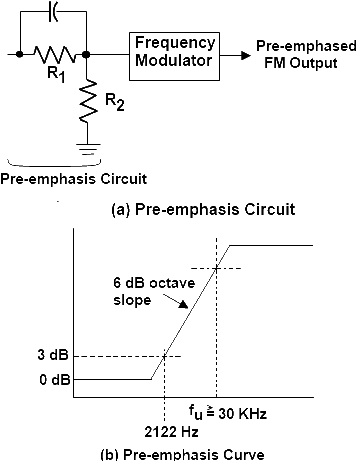
At the transmitter, the modulating signal is passed through a simple network that amplifies the high frequency, components more than the low-frequency components. The simplest form of such a circuit is a simple high-pass filter of the type shown in Fig (a). Specification dictates a time constant of 75 microseconds (µs) where t = RC. Any combination of resistor and capacitor (or resistor and inductor) giving this time constant will be satisfactory. Such a circuit has a cutoff frequency fco of 2122 Hz. This means that frequencies higher than 2122 Hz will be linearly enhanced. The output amplitude increases with frequency at a rate of 6 dB per octave. The pre-emphasis curve is shown in Fig (b). This pre-emphasis circuit increases the energy content of the higher-frequency signals so that they will tend to become stronger than the high-frequency noise components. This improves the signal-to-noise ratio and increases intelligibility and fidelity.

The pre-emphasis circuit also has an upper break frequency fu where the signal enhancement flattens out.
See Fig (b). This upper break frequency is computed with the expression.
fu = R1 +(R2/2πR1R1C)
It is usually set at some very high value beyond the audio range. A fu of greater than 30KHz is typical.
De-emphasis Circuit

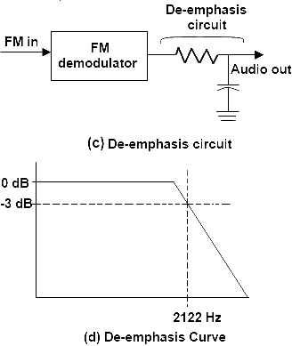
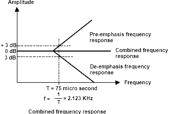
To return the frequency response to its average level, a de-emphasis circuit is used at the receiver. This is a simple low-pass filter with a constant of 75 πs. See Figure (c). It features a cutoff of 2122 Hz and causes signals above this frequency to be attenuated at the rate of 6bB per octave. The response curve is shown in Fig (d). As a result, the pre-emphasis at the transmitter is precisely offset by the de-emphasis circuit in the receiver, providing a normal frequency response. The combined effect of pre-emphasis and de-emphasis is to increase the high-frequency components during transmission so that they will be stronger and not masked by noise.

Differences between pre-emphasis and de-emphasis in audio signals:
Pre-Emphasis
- Applies a high-pass filter to boost high frequencies prior to transmission or recording
- Boosts treble range signals that may get attenuated during transmission
- Improves signal-to-noise ratio for high frequencies
- Commonly used time constants are 50μs and 75μs
- Can introduce distortion if the boost is too aggressive
- Found in FM radio, cassette recording, NTSC video
De-Emphasis
- Applies a high-cut filter to attenuate boosted high frequencies
- Reverses the frequency contour applied by pre-emphasis
- Reduces noise in high frequencies that got boosted
- Must use same time constant as pre-emphasis stage
- Restores flat frequency response of the original signal
- Found in FM receivers, tape playback, NTSC video
Key Differences:
- Pre-emphasis boosts treble, de-emphasis cuts treble
- Pre-emphasis occurs before transmission/storage
- De-emphasis happens during reception/playback
- Pre-emphasis improves SNR, de-emphasis reduces noise
- Must use matched time constants to reverse effect
In summary, pre-emphasis boosts high frequencies prior to transmission to improve SNR, while de-emphasis attenuates the boosted treble on reception to restore the original spectrum. The stages complement each other.
Key advantages and disadvantages of pre-emphasis and de-emphasis in communication systems:
Pre-Emphasis:
Advantages:
- Improves signal-to-noise ratio - Boosts high frequencies before transmission which are more susceptible to noise
- Increases transmission range - Pre-emphasis provides 6-10 dB gain allowing greater transmission distance
- Compatible with transmitter characteristics - Takes advantage of nonlinear compression in transmitters
- Reduces channel crosstalk - Attenuates lower frequencies to prevent crosstalk between channels
Disadvantages:
- Increases transmit power - Requires more transmitter power to accommodate pre-emphasis
- Susceptible to non-linearity - Can introduce distortion if pre-emphasis is applied incorrectly
De-Emphasis:
Advantages:
- Restores original frequency response - Rolls-off highs to counteract effects of pre-emphasis
- Reduces noise - Attenuates amplified high frequencies and the noise introduced during transmission
- Improves overall SNR - Combined pre-emphasis and de-emphasis give better SNR
- Prevents adjacent channel interference - Reduces high frequencies that may cause interference
Disadvantages:
- Requires complex circuitry - Needs tuned circuits or active filters to provide specific de-emphasis
- Risk of incorrect de-emphasis - Can further distort signal if de-emphasis doesn't match pre-emphasis
So in summary, pre-emphasis and de-emphasis extend transmission range and improve SNR, but require careful matching and tuning to prevent distortion.
Key applications where pre-emphasis and de-emphasis are used:
- FM radio broadcasting - Pre-emphasis boosts high frequencies before transmission, while de-emphasis is applied in receivers to reduce noise and distortion. This improves FM signal quality.
- Magnetic tape recording - Tape recording applies pre-emphasis to utilize the full dynamic range, while playback applies de-emphasis to restore the original frequency response.
- Disc recording technologies - Optical and magnetic discs like CDs, DVDs, and Blu-ray employ pre-emphasis and de-emphasis to maximize SNR and minimize errors.
- Microwave radio links - Pre-emphasis allows longer hops in microwave line-of-sight communication links. De-emphasis restores the original spectrum.
- Satellite communication - Pre-emphasis is applied to signals sent to communication satellites to overcome noise in space. The satellite or receiver de-emphasizes the signal.
- Telephony - Both cellular and landline telephony apply pre-emphasis to speech before transmission and de-emphasis at the receiving end for clarity.
- Professional wireless systems - Wireless microphones and in-ear monitors use pre-emphasis and de-emphasis for clean audio over the radio.
- HDTV broadcasting - Some HDTV standards have pre and de-emphasis circuits for luminance and chrominance signals.
- Dolby noise reduction - Dolby systems use a form of sliding pre and de-emphasis to attenuate frequencies with less audio content, reducing noise.
So in summary, pre-emphasis paired with de-emphasis provides vital SNR enhancement in many recording, broadcast, radio, and telephony applications.
