SCR In Parallel
To control the maximum power, an SCR's rated forward current and rated forward blocking voltage are crucial. In order to increase one rating, the other must be reduced. Despite being available with high voltage ratings, some applications like transmission lines require more voltage than what a single SCR can provide. Connecting two or more SCRs in series is necessary in such cases. For high-current applications, SCRs must be connected in parallel. Series-parallel combinations of SCRs are used for high-voltage, high-current applications.
SCRs in Parallel
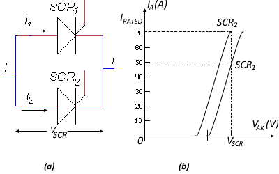
When the load current exceeds the rating of a single SCR, SCRs are connected in parallel to increase their common current capability. If SCRs are not perfectly matched, this results in an unequal sharing of current between them. Figure 1 shows the V-I characteristics of two SCRs, SCR1 and SCR2. The ratings of the SCRs are the same. When these SCRs are connected in parallel, they will have equal voltage drops VSCR across them. However, due to their mismatch in characteristics. SCR2 is carrying the rated current (I2), while SCR1 is carrying a current I1, which is much less than its rated value. The total rated current of the parallel connection is only I1 + I2 instead of 2l2.

(a) two SCRs in parallel (b) on-state characteristics
Matched-pair SCR’s are generally available for parallel connection, but they are very expensive. With unmatched SCR’s equal current sharing is enforced by adding a low-value resistor or inductor in series with each SCR. Forced current sharing using equal-value resistors is shown in Figure 2. The basic requirement is to make current I1 close to I2; a maximum difference of 20% is accepted across SCR2, and the value of R can be obtained from.
I1R + V1 = I2R + V2
R = (V1 – V2) / (I2 – I1)
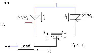
Equalization using a resistor is inefficient due to the extra power loss in the resistor. Moreover, resistors do not compensate for unequal SCR turn ON or turn OFF times. One of the SCRs may turn ON or turn OFF before the other. In either case, the ON SCR must carry the full load current momentarily until both are switched, and it can easily be damaged due to overloading. Figure 3 shows a center-tapped reactor in which the SCR carrying the greater current will induce a voltage proportional to the imbalance in current and with the polarity shown. Voltage in reactor L1 opposes the flow of current, and voltage in L2 causes an increase in current flow through the SCR that originally carried the lower current. As a result, a balanced current distribution is achieved. The reactors, although expensive, are more efficient.

Since the main problem in high current applications is excessive junction temperature, SCR’s used in parallel must be derated by at least 15%. For example, two 50 A SCR’s connected in parallel may carry only 85 (47.5 + 47.5) A. In addition, the SCR’s are normally mounted on a common heat sink to equalize temperatures.
Applications of Silicon Controlled Rectifiers (SCRs) Used in Parallel
- Power control - Multiple SCRs can be connected in parallel to control higher currents and power levels in devices like motor drives, power supplies, heating elements, etc.
- Overcurrent protection - Parallel SCRs share current, providing fault tolerance. If one SCR fails, others will still conduct and avoid system failure.
- Large variable resistors - SCRs in parallel can act as variable resistances in applications like light dimmers to control large loads.
- Snubber circuits - Small snubber capacitors placed across each SCR in parallel arrays help reduce transients during switching.
- Phase control - Parallel SCR arrays allow control of larger AC voltages by adjusting the phase angle trigger in applications like lamps, and heaters.
- DC converters - Parallel devices used in controlled rectifier circuits for high-power DC power supplies from AC input.
- Soft starters - Using SCRs in parallel enables gradual start-up and reduces inrush current in large motors and transformers.
- Battery chargers - Parallel SCRs regulate the charging current for high-capacity industrial battery banks and UPS systems.
- Static VAR compensators - Parallel SCR banks dynamically adjust reactive power on transmission lines to stabilize the voltage.
- DC power transmission - Parallel SCR valves enable efficient HVDC power transmission and conversion between AC and DC grids.
Parallel SCR arrays are commonly used where high current, fault tolerance, and precise power control is needed in power electronics applications. The parallel devices distribute current and enable scaling.
Example 1
For the circuit in Figure 2, find the value of the current-sharing resistors if VS = 1000 V, RL = 1Ω, and the rated current of each SCR is 700A. Also, find the power loss in the resistors.
Solution:
Choose
V1 = 1.55V
V2 = V1 = 1.45V
IL = 1000/1 = 1000A
Let one thyristor carry
I1 = 400A
Therefore
I2 = 1000 – 400 = 600A
R = (1.55 – 1.45) / 200 = 0.5 mΩ
PLOSS = (600)2(0.0005) + (400)2(0.0005) = 260 W
Example 2
In the circuit in Figure 2, the source voltage is 500V and the load resistance is 5Ω. Two SCR’s with the characteristics shown in Figure 1(b). each rated at 70A, are connected in parallel to share the load current. Find the value of the resistor that will give the proper current sharing. Also, find the voltage drop across the parallel combination and the power dissipated by the current-sharing resistors.
Solution:
The load current is
IL = 500 / 5 = 100 A
Let us choose a current difference of 15% between the two SCR’s, so
I2 = 50 + 15 = 65 A
I1 = 50 – 15 = 35 A
From the characteristic curve
V1 = 1.6 V
V2 = 1.5 V
Therefore
R = (V1 – V2) / (I2 – I1) = (1.6 – 1.5) / (65 – 35) = 3.3 mΩ
The voltage drops across the two resistors are
I1R = 35 (0.0033) = 0.12 V
I2R = 65 (0.0033) = 0.22 V
The voltage drop across the parallel branch is
V1 + I1R = V2 + I2R
=1.6 + 0.12 = 1.5 + 0.22 = 1.72V
The power loss in the resistor is
I21 R = 352 (0.0033) = 4.1 W
I22 R = 652 (0.0033) = 14.1 W
