Directional Coupler
Directional couplers are essential components used in radio frequency (RF) systems for signal monitoring, power measurement, and signal distribution. They play a crucial role in various applications, including telecommunications, wireless communication, radar systems, and satellite communication. In this blog post, we will explore what directional couplers are, how they work, their applications, and the advantages they offer in RF systems.
What is a Directional Coupler?
A directional coupler is a passive RF device that enables the coupling of electromagnetic energy from one transmission line to another while allowing it to travel in only one direction. It consists of four ports: the mainline, the coupled port, the isolated port, and the termination port. The mainline is the input/output port where the primary signal is applied, while the coupled port diverts a portion of the energy to another line without affecting the mainline signal.
How does a Directional Coupler work?
Directional couplers use the principle of electromagnetic coupling to split or combine signals. They often incorporate a combination of transmission lines and couplers with specific coupling ratios to achieve the desired functionality. When a signal is applied to the mainline, a portion of it is coupled to the coupled port due to the electromagnetic interaction between the lines. The isolated port remains largely unaffected by the mainline signal, providing isolation between the mainline and the coupled line.
Construction
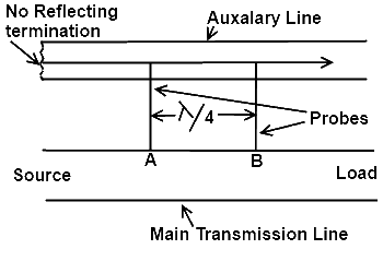
As shown in the diagram provided, the directional coupler consists of an auxiliary piece of transmission line, with one end connected to the detection meter and the opposite end connected to a pure resistor known as a non-reflecting end. Two slots in the directional coupler serve as access points for measurement probes to measure the power. The distance between these probes or slots is maintained at λ/4 of the operating frequency

Working of Directional Coupler
The directional coupler is used to measure the true power provided by the source to the load. In this case, if there is a matched load, then the standing wave along the transmission line will be the same as the incident wave. However, if the load is mismatched, then the standing wave or the power present on the transmission lines will not be the same as the power provided by the source.
The arrangement of the directional coupler enables us to measure the true power provided by the source to the load, looking towards the diagram. If we consider the travel from the source to the load, we can see that at point A, the forward wave is provided to the directional coupler with the help of the probe. At point B, the wave has traveled the distance of λ/4 both on the main transmission line and the auxiliary line of the directional coupler.
The wave traveling in the opposite direction of the detection meter from the probe will find itself at the non-reflecting termination where its whole energy will be absorbed. The wave traveling towards point B will become stronger due to the additive effect of energy provided by the main line to the probe at point B.
Now, in the case of reflected energy at point B traveling towards point A, it will find itself out of phase at point B with the incident energy, but in phase at point A with the same incident energy. This is because the behavior of the reflected wave will be vice versa at point A with respect to point B, due to the distance between these two points being λ/4.
In this way, we come to the conclusion that in the case of a mismatched load, the power present on the transmission line and the reflected power present at point A of the directional coupler will be added up. This is the result of the true power produced for measurement at the detection meter.
Applications of Directional Coupler
- Signal Monitoring and Power Measurement: Directional couplers are commonly used to monitor and measure RF signals in various systems. They can be employed to sample a fraction of the mainline signal, allowing the monitoring of power levels without significantly affecting the main signal path.
- Signal Sampling and Network Analysis: Directional couplers play a vital role in network analysis and testing. By coupling a portion of the signal, they facilitate signal sampling, allowing engineers to analyze the characteristics of the signal in real time.
- Signal Distribution: In certain applications, such as in distributed antenna systems (DAS) or power dividers, directional couplers are used to split the RF signal into multiple paths to serve different devices or antennas.
- Isolation and Load Matching: Directional couplers can be employed to provide isolation between RF components, preventing undesired signal reflections and ensuring proper load matching for better signal transmission efficiency.
Advantages of Directional Coupler
- Non-invasive Signal Monitoring: Directional couplers provide a non-invasive means of monitoring signals without disrupting the primary signal path, making them ideal for in-service monitoring and testing.
- Compact and Reliable: They are compact, passive devices that require no external power, making them highly reliable and suitable for a wide range of RF applications.
- Broadband Operation: Directional couplers can be designed for broad frequency ranges, allowing them to work effectively across various RF bands.
- High Isolation: They offer high isolation between the mainline and the coupled port, minimizing interference and signal distortion.
Conclusion:
Directional couplers are indispensable components in RF systems, serving critical functions such as signal monitoring, power measurement, signal distribution, and isolation. Their non-invasive nature, reliability, and versatility make them vital for efficient RF network operation. As technology continues to advance, directional couplers will remain a fundamental building block in modern wireless communication and RF engineering applications.
